While working on an 801A A2 amplifier design, I experimented with using its high-mu cousin, the 841, in the voltage gain stage. Ultimately it did not work out, and so I have quite a few of these 841 tubes available, along with ready-to-go filament transformers and Rod Coleman's regulators. They are burning a hole in my pocket.
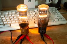
I am all SET on speakers amplifiers at the moment (see what I did there?), but I am in need of a quality headphone amplifier. It so happens I have a pair of Sowter 8665 headphone output transformers on order. I married the 841, Sowter 8665, and my desire to build a headphone amplifier into the design below.
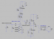
A couple of notes:
1) The 841 has a mu of ~25 when CCS loaded, from my measurements, and a plate impedance of roughly 25K, necessitating the buffer to drive the output. Here is the datasheet: https://tubedata.altanatubes.com.br/sheets/049/8/841.pdf
2) I've used SiC filament bias on the 841: 400Va / 5mA Ia / 3.25Vk bias point
3) The Sowter 8665 is "designed to be driven from a cathode follower output stage via a coupling capacitor", according to Sowter. I have seen these used before in "spud" parafeed designs most commonly. The transformers are rated for 500mW at 20Hz - as drawn the amplifier will put out ~400mW into a 32ohm load at maximum 1.8Vrms input signal, which would make me deaf. Here is the OPT datasheet: https://www.sowter.co.uk/pdf/8665.pdf
4) The Sowter 8665 has three primary windings that can be paralleled, I will likely include a switch to change from 12:1 to 4:1 turns ratio for higher impedance headphones (300ohm)
I recognize this design is somewhat silly with the high B+, impracticality of the 841, heat dissipation, etc., but that is the joy of diyAudio, building things because you can, not because you should open to ideas, otherwise I will update here if and when it comes to life.

I am all SET on speakers amplifiers at the moment (see what I did there?), but I am in need of a quality headphone amplifier. It so happens I have a pair of Sowter 8665 headphone output transformers on order. I married the 841, Sowter 8665, and my desire to build a headphone amplifier into the design below.

A couple of notes:
1) The 841 has a mu of ~25 when CCS loaded, from my measurements, and a plate impedance of roughly 25K, necessitating the buffer to drive the output. Here is the datasheet: https://tubedata.altanatubes.com.br/sheets/049/8/841.pdf
2) I've used SiC filament bias on the 841: 400Va / 5mA Ia / 3.25Vk bias point
3) The Sowter 8665 is "designed to be driven from a cathode follower output stage via a coupling capacitor", according to Sowter. I have seen these used before in "spud" parafeed designs most commonly. The transformers are rated for 500mW at 20Hz - as drawn the amplifier will put out ~400mW into a 32ohm load at maximum 1.8Vrms input signal, which would make me deaf. Here is the OPT datasheet: https://www.sowter.co.uk/pdf/8665.pdf
4) The Sowter 8665 has three primary windings that can be paralleled, I will likely include a switch to change from 12:1 to 4:1 turns ratio for higher impedance headphones (300ohm)
I recognize this design is somewhat silly with the high B+, impracticality of the 841, heat dissipation, etc., but that is the joy of diyAudio, building things because you can, not because you should
Last edited:
Cathode followers, that's where I draw the line! Yes, it is a funny design  the B+ is nutso for a 0.5W headphone amp, would probably use a doubler and a voltage reg.
In my defense, there is a whole market of high-end tube headphone amplifiers that make this look like the most practical design in the world. Look at this thing, $8,000 running push-pull 2A3s...for headphones! What headphone needs that much power?
WA33 Fully-balanced Headphone Amp/Preamplifier — Woo Audio
Last edited:
Good Luck!
FET follower should work well in that position, I suspect. The AOT1N60 is a good part for the job, even down to 10V headroom.
A minor observation: I would omit the extra gate zener D1, as it will do nothing useful, and may degrade the voltage-robustness.
The gate should not go negative in normal operation, and if if should be tempted to go there due to some transient condition that sets the drain current to zero (and so the supply voltage rises), it's better to let the zener D2 clamp Vgs to -0.6V. Some Trench FETs show a lower breakdown Vds: namely Vdsx compared to Vdss, and Vdsx would apply with a negative gate bias. The AOT1N60 does not specify, though.
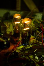
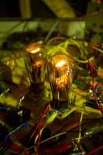
I prototyped the 841 headphone amp in my cold garage! First snow of the season, what a day to decide to do this...
Prepare for ugly, lots of alligator clips, not everything on the plank is part of the headphone amp, mind you.
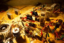
I stacked two pairs of 6.9VAC windings on a Lundahl LL1650 mains transformer for the 841 heater filaments. I used resistor (3ohm) filament bias on the 841, bias ended up being 370Va, 5mA Ia, 3.75Vk. Maida regulated B+ was 460V off the 350VAC HT winding of the LL1650. I set the bias current for the AOT1N60 source follower to 15mA. Output capacitor is a 4.7uF polypropylene Solen. The Sowter 8665 are wired 4:1 for use with high impedance headphones.
Distortion spectrum at 1mW into a 300ohm dummy load, left channel.
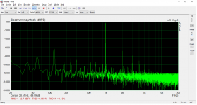
As you can see, the distortion is very low and follows a nice single-ended spectrum. What isn't low is that 120Hz noise peak! I suspect this is due to rectifier coupling into the B+ mains winding from the filament supply, although I would suspect the Maida to squash that way down, I will have to look into it further. I'm sure the long wires runs and alligator clips are not helping. Oddly enough, the 120Hz noise is not audible while listening. Worst case, if it is coupling from the filament supply, I will have to use dedicated filament transformers. Would be a bummer, just means more chassis real estate.
Here is the frequency response.
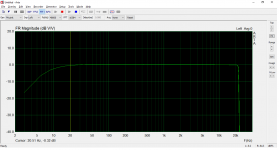
Nice and flat with a smidge of rolloff at 20Hz. Will try increasing the value of the output cap and see if we can get a full 20Hz-20kHz.
How does it sound...really, really good! Excellent clarity, soundstage, bass definition, no doubt in large part due to the very low distortion, I like it a lot. Also, this should be able to drive just about any headphone, 10mW of output into the HD650 is a very unhealthy listening volume, and we've got a lot of power to spare.
Given the early impressions, likely to take it all the way to completion once I sort out the heater winding vs. filament transformer question. Will also experiment with altering the bias point and will try SiC diode filament bias later this week rather than the 3ohm resistor.
Prepare for ugly, lots of alligator clips, not everything on the plank is part of the headphone amp, mind you.

I stacked two pairs of 6.9VAC windings on a Lundahl LL1650 mains transformer for the 841 heater filaments. I used resistor (3ohm) filament bias on the 841, bias ended up being 370Va, 5mA Ia, 3.75Vk. Maida regulated B+ was 460V off the 350VAC HT winding of the LL1650. I set the bias current for the AOT1N60 source follower to 15mA. Output capacitor is a 4.7uF polypropylene Solen. The Sowter 8665 are wired 4:1 for use with high impedance headphones.
Distortion spectrum at 1mW into a 300ohm dummy load, left channel.

As you can see, the distortion is very low and follows a nice single-ended spectrum. What isn't low is that 120Hz noise peak! I suspect this is due to rectifier coupling into the B+ mains winding from the filament supply, although I would suspect the Maida to squash that way down, I will have to look into it further. I'm sure the long wires runs and alligator clips are not helping. Oddly enough, the 120Hz noise is not audible while listening. Worst case, if it is coupling from the filament supply, I will have to use dedicated filament transformers. Would be a bummer, just means more chassis real estate.
Here is the frequency response.

Nice and flat with a smidge of rolloff at 20Hz. Will try increasing the value of the output cap and see if we can get a full 20Hz-20kHz.
How does it sound...really, really good! Excellent clarity, soundstage, bass definition, no doubt in large part due to the very low distortion, I like it a lot. Also, this should be able to drive just about any headphone, 10mW of output into the HD650 is a very unhealthy listening volume, and we've got a lot of power to spare.
Given the early impressions, likely to take it all the way to completion once I sort out the heater winding vs. filament transformer question. Will also experiment with altering the bias point and will try SiC diode filament bias later this week rather than the 3ohm resistor.

Last edited:
Thanks, Rod, I'll give that a try, simple as a turn of a trimmer. Going to try SiC diode filament bias as well vs. resistor.
This morning, I gave the dedicated filament transformers a shot vs. running the filaments off the paralleled heater windings of my Lundahl mains transformer, FFT below.
1mW into 300ohms dummy, left channel, dedicated filament traffo.
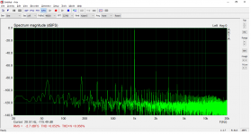
The 120Hz peak has completely disappeared, so I think I have my answer, looks like the filament transformers will be necessary after all, bummer! The LL1650 would have been a nice all-in-one solution otherwise.
Just for fun, I pushed the amp a little bit and watched the distortion spectrum in real time. As I recall, at 300mW into 300ohms, the distortion was only 0.25%! So it's good to know the distortion will be nearly inaudible just before I go deaf.
This morning, I gave the dedicated filament transformers a shot vs. running the filaments off the paralleled heater windings of my Lundahl mains transformer, FFT below.
1mW into 300ohms dummy, left channel, dedicated filament traffo.

The 120Hz peak has completely disappeared, so I think I have my answer, looks like the filament transformers will be necessary after all, bummer! The LL1650 would have been a nice all-in-one solution otherwise.
Just for fun, I pushed the amp a little bit and watched the distortion spectrum in real time. As I recall, at 300mW into 300ohms, the distortion was only 0.25%! So it's good to know the distortion will be nearly inaudible just before I go deaf.
Thanks audiowize, HF extension looks pretty good on my FR plot, I'll see what can be done with the sound card, it has misled me before. I increased the value of my output cap which got me very close to flat LF response, down 0.1-0.2dB at 20Hz.
I have the SiC diodes on hand, going to stack 3-4 of them, solder on some alligator clips, and see how the sound/measurements compare in A-B vs. resistor filament bias later today.
I have the SiC diodes on hand, going to stack 3-4 of them, solder on some alligator clips, and see how the sound/measurements compare in A-B vs. resistor filament bias later today.
I did an AB of the SiC diodes vs. resistor filament bias. Measurements were essentially unchanged, I think the resistor sounded better but hard to say, will go with the resistor for now.
I've seen enough to move forward with building this 841 headphone amplifier. I essentially have all of the parts already! Just need a few more knick knacks and a chassis.
I ordered some matching steel transformer shields, I will mount the mains and filament transformers on top, output transformers on the interior.
Working on a layout draft, I will have the chassis machined by Dave at Landfall Systems. I recently inspired him to put together a powder coating setup! I have been powder coating my own chassis, but I will probably have him do this one (it is too cold in my garage to do any powder coating).
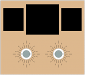
Since there are only two tubes in this amplifier, the front half of the top plate will have quite a bit of real estate. I will put that to use with something I have wanted to do, I will recess the tube sockets, à la Yamamoto style.
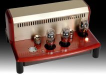
To me, the glow of thoriated tungsten tubes is reminiscent of sunlight, so I am going to do something like below, recessed sockets with the surrounding ventilation pattern a sunburst. This is a rough draft so obviously subject to change in terms of dimensions and layout.
I've seen enough to move forward with building this 841 headphone amplifier. I essentially have all of the parts already! Just need a few more knick knacks and a chassis.
I ordered some matching steel transformer shields, I will mount the mains and filament transformers on top, output transformers on the interior.
Working on a layout draft, I will have the chassis machined by Dave at Landfall Systems. I recently inspired him to put together a powder coating setup! I have been powder coating my own chassis, but I will probably have him do this one (it is too cold in my garage to do any powder coating).
Since there are only two tubes in this amplifier, the front half of the top plate will have quite a bit of real estate. I will put that to use with something I have wanted to do, I will recess the tube sockets, à la Yamamoto style.

To me, the glow of thoriated tungsten tubes is reminiscent of sunlight, so I am going to do something like below, recessed sockets with the surrounding ventilation pattern a sunburst. This is a rough draft so obviously subject to change in terms of dimensions and layout.

The 8665 has three secondary windings that can be placed in series or parallel for adjustment, here is the diagram from Sowter's site:
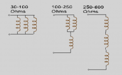
I will be putting in a three-throw switch such that the turns ratio of the output transformer can be adjusted for headphones of different impedances, worked out the wiring for the switch this morning.
I also measured the output impedance of the amplifier with the 8665 wired for use with high impedance headphones, 250-600ohm, in a 4:1 turns ratio.
Output Z is 19.9 ohm.
So, with the low impedance wiring for 30-100ohm headphones, a 12:1 turns ratio, output Z should be somewhere around 2-3ohm.
This amplifier build is confirmed and all plans finalized. I've placed my chassis order and am acquiring final parts.
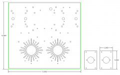
Here is the chassis top plate with sunburst ventilation design. The tube sockets will be recessed down into the chassis about half the width of the tube base.
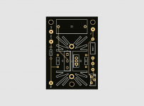
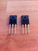
My source follower PCBs have been redesigned to accomodate TO-247-3 package FETs.
I recently went to look over stock of the FET I plan to use, the Cree C2M1000170D, these are now backordered for almost a year! Fortunately I have two left.
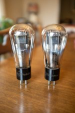
I have also acquired a very nice pair of globe RCA 841 for this amplifier when it is all done.
Will post some pictures and measurements of the amplifier when it is completed, probably in a few weeks.
Here is the chassis top plate with sunburst ventilation design. The tube sockets will be recessed down into the chassis about half the width of the tube base.

My source follower PCBs have been redesigned to accomodate TO-247-3 package FETs.

I recently went to look over stock of the FET I plan to use, the Cree C2M1000170D, these are now backordered for almost a year! Fortunately I have two left.

I have also acquired a very nice pair of globe RCA 841 for this amplifier when it is all done.


Will post some pictures and measurements of the amplifier when it is completed, probably in a few weeks.
Very cool!
The 841s that I got were almost all ST glass Hytron tubes but I got one globe and one was a Raytheon 4-pillar type. That one looks really weird. I wish I had more.
I've started designing all PCBs with TO-247 footprint, then if I want to use a TO-220 I just form the leads to fit.
The 841s that I got were almost all ST glass Hytron tubes but I got one globe and one was a Raytheon 4-pillar type. That one looks really weird. I wish I had more.
I've started designing all PCBs with TO-247 footprint, then if I want to use a TO-220 I just form the leads to fit.
- Status
- This old topic is closed. If you want to reopen this topic, contact a moderator using the "Report Post" button.
- Home
- Amplifiers
- Tubes / Valves
- 841 DHT Hybrid Headphone Amplifier
