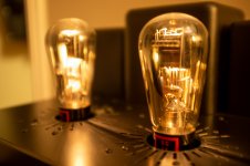
Thanks, SS, first time I have done the recessed sockets, I like the look! The sockets are CMC teflons, I got them from Hificollective in the UK, but you can probably find them somewhere in the states or on eBay, they are Chinese made. My only gripe with them is the nuts on the bottom that hold the pins in place loosen pretty easily.
The amplifier is done, photos in a few minutes...
The amplifier is done, photos in a few minutes...
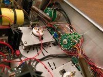
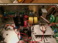
Finished up this amplifier today, here are some photos of the circuit. Wiring the output impedance selector switch, that alters the turns ratio of the output transformer, was a real PITA, but it works most importantly.
Circuit first.
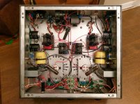
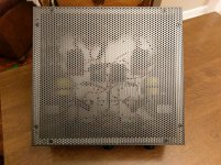
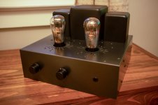
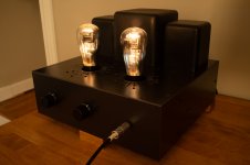
And here is the finished look.
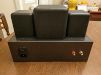
Rear panel.
And a long exposure on my desk.
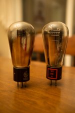
Something interesting, the globe RCA 841 have very low distortion relative to the shouldered Hytron 841 in this amplifier. RCA 841 numbers into various headphone impedances:
THD 1mW into 32ohm (low impedance switch) - 0.017%
THD 1mW into 120ohm (medium impedance switch) - 0.007%
THD 1mw into 300ohm (high impedance switch) - 0.0054%
Whereas the Hytron distortion levels are double or triple the RCAs.
With the RCAs, this amplifier sounds incredible with my HD650 and ZMF Auteur headphones, but very revealing of poor recordings it seems, to my ears anyway. Good ones sound fantastic, bad ones sound bad. I might experiment with different output capacitors and source follower FETs.
Circuit first.


And here is the finished look.

Rear panel.

And a long exposure on my desk.

Something interesting, the globe RCA 841 have very low distortion relative to the shouldered Hytron 841 in this amplifier. RCA 841 numbers into various headphone impedances:
THD 1mW into 32ohm (low impedance switch) - 0.017%
THD 1mW into 120ohm (medium impedance switch) - 0.007%
THD 1mw into 300ohm (high impedance switch) - 0.0054%
Whereas the Hytron distortion levels are double or triple the RCAs.
With the RCAs, this amplifier sounds incredible with my HD650 and ZMF Auteur headphones, but very revealing of poor recordings it seems, to my ears anyway. Good ones sound fantastic, bad ones sound bad. I might experiment with different output capacitors and source follower FETs.
I made one major change on this amplifier between my original prototype and the final design: I swapped the AOT1N60 source follower FET for a Cree C2M1000170D.
I found that there was something of an upper midrange and treble sibilance / bite in the completed design. Did some investigating and finally swapped back the AOT1N60.
Oddly enough, despite the measurements being essentially identical, this sound artifact was gone! So the AOT1N60 stays. Not sure why the Cree chip didn't sit right.
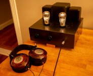
Here is the amp with my ZMF Auteur headphones.

Wow, amazing build and construction.
Couple of questions:
1. Where did you buy the transformer covers? I see them on ebay but shipping is from China and I hesitate to order.
2. For making measurements or adjusting Rod's regulators, you'd have to operate the amp sideways. Is it okay to operate DHTs, such as the 841, 801, 26, 01a, etc., in a horizontal orientation? Some of the filaments are hung from the top, so I presumed the only right way is to hold them up vertical. Probably won't damage them, but could it result in less than optimum operation?
I'm not sure why there would be much difference between the two fets. It would be interesting to find out what's going on there, but probably not worth the effort if it is fixed.
It looks fantastic.
Cree SiC Fets tend to oscillate at hundred MHz region, if the layout not optimal.
Try to use ferrite pearls on all legs.
Sometime the little (10R) resistor is need as drain stopper.
Thanks, SS. Didn't have any indication from the initial measurements that the FET was oscillating, all seemed to be working as intended, the upper midrange just had a "bite" that was fatiguing to listen to over time. If I ever try the Cree chip again, I will investigate, but the sound is very nice with the A&O chip, going to leave it in for now.
euro21 - have you found changing the RC regulator resistor on the Coleman regs makes has an audible impact?
Wow, amazing build and construction.
Couple of questions:
1. Where did you buy the transformer covers? I see them on ebay but shipping is from China and I hesitate to order.
2. For making measurements or adjusting Rod's regulators, you'd have to operate the amp sideways. Is it okay to operate DHTs, such as the 841, 801, 26, 01a, etc., in a horizontal orientation? Some of the filaments are hung from the top, so I presumed the only right way is to hold them up vertical. Probably won't damage them, but could it result in less than optimum operation?
The transformer covers were purchased from China, had no issues with the order on eBay. I see no issue with the amplifier being sideways while making adjustments on the interior. The filaments are tensioned with springs, they aren't going anywhere, unless the springs break
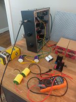
In fact, I have been trying different output capacitors in this amplifier today, it is lying on its side with the caps clipped in with alligator clips, sounds great
L0rdGwyn said:have you found changing the RC regulator resistor on the Coleman regs makes has an audible impact?
Yes.
There is a noticeable difference between pure WW and non inductive (for example Ayrton-Perry winding) wirewound resistors if you use R.C. regulator in low level preamp filaments.
Interestingly Welwyn WW 2x resistors don't have Ayrton-Perry structure, but the "tone" is look alike non inductive WW resistor.
I regularly use Mills in preamp an Welwyn in power tube's filament regulator.
Okay, I am going to give it a try, thanks for the tip. If it is an improvement, I will have to add to my 45 amp and future 801A amp, look how much work you've made for me  I have used Mills when using cathode bias on power triodes, also in my speaker crossovers, so happy to use them again.
I have also thought of trying non-inductive wirewound in filament bias on the 841 in this amplifier. The resistance is only 3ohm but it is in the signal path, have you tried inductive vs. non-inductive in filament bias?
I have also thought of trying non-inductive wirewound in filament bias on the 841 in this amplifier. The resistance is only 3ohm but it is in the signal path, have you tried inductive vs. non-inductive in filament bias?
Last edited:
"have you tried inductive vs. non-inductive in filament bias? "
At the "beginning", when I tried filament bias I was very surprised.
I saw that Vinylsavor use it (filament bias), I thought I'd try.
I just then measuring few #26 tubes (CCS load, cathode bias, labor PSU for filament) with spectrum analyser (I also test its with CD->DUT->amplifier->speaker).
I found some old -sixty years old- Remix wirewound resistors in the drawer.
It was working, DC operating point setting properly, gain was OK... but in the spectra was something strange, stochastically changed. It wasn’t conspicuous, so I ignored it.
I tied it to test amplifier to listening.
There was a shock, I heard regional AM broadcaster radio quietly, near to base noise!
I examined everything, but it all was the same, except filament bias.
I rebuilt the previous bias method, it was silent.
Using filament bias -regardless of the tube- the AM radio was audible.
I examined again the spectrum, the stochastic changing was small, but visible.
Blocking filament bias resistor with capacitor the disturbance has disappeared, so the guilty was the resistor .... or the PSU.
Changing PSU to another (both has few ten uV noise on his output), the symptom persisted.
With broadband AC voltmeter the phenomenon (on the resistor) was visible, the old wirewound act as an antenna.
I have some resistor, so I connect two parallel in opposite (hum bucker), and two of this in serial (poor men's non inductive resistor). The phenomenon decreased, but did not disappeared.
I found aluminium housed 1R resistors in my drawer, I connected it serially.
The symptom significantly decreased, the spectrum was almost steady.
So the nude, simple wirewound resistor was sensitive to radiated electrical pollution.
Later I tried it with some simple wirewounds.
All was sensitive to varying degrees, but even a simple shielding - aluminium foil, any metal case - helped.
For me the solution is a non inductive resistor.
Because it dissipates many Watts, I prefer aluminium housed ones (on the appropriate heatsink).
Hey euro21 - I did try a NOS Mills wirewound on the output of the Rod Coleman regulators in this amplifier, I do think it was an improvement, thanks.
I am going to try to tame the Cree C2M1000170D. Do you have a recommendation for ferrite beads that will fit the TO-247 leads?
I am going to try to tame the Cree C2M1000170D. Do you have a recommendation for ferrite beads that will fit the TO-247 leads?
I've made a few improvements to this design.
I was hearing some treble sibilance and was seeing some low level HF garbage on square wave, so set out on a quest to exorcise any oscillation demons.
I redesigned the source follower PCBs to add proper 100uF decoupling caps, improve the layout, add some resistance to the AOTN160 drain, improved ground plane. I also placed slip on ferrite beads to the gates of both the source follower and current sink FETS.
Here are the new source follower boards.
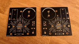
Other changes made on my crusade - increased the value of the 841 grid stopper to 4.7K from 1K (increased stepwise while monitoring HF response), changed from a Ohmite 3ohm 20W wirewound for filament bias to a pair of paralleled Mills MRA12 non-inductive 6ohm resistors. Output resistors on the Rod Coleman filament regulators were also changed to Mills MRA5 non-inductive wirewounds.
The schematic now looks roughly as follows (ferrite beads not included).
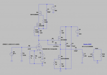
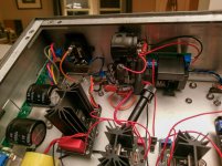
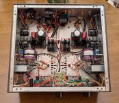
New interior. Still some wiring improvements to be made to reduce AC coupling.
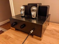
The treble sibilance is gone, as is the HF garbage, so seems the changes were effective. Undoubtedly the best it has sounded. With the output switch set to "high impedance" 4:1 turns ratio, THD at 1mW into 300ohms is 0.0063%.
I was hearing some treble sibilance and was seeing some low level HF garbage on square wave, so set out on a quest to exorcise any oscillation demons.
I redesigned the source follower PCBs to add proper 100uF decoupling caps, improve the layout, add some resistance to the AOTN160 drain, improved ground plane. I also placed slip on ferrite beads to the gates of both the source follower and current sink FETS.
Here are the new source follower boards.

Other changes made on my crusade - increased the value of the 841 grid stopper to 4.7K from 1K (increased stepwise while monitoring HF response), changed from a Ohmite 3ohm 20W wirewound for filament bias to a pair of paralleled Mills MRA12 non-inductive 6ohm resistors. Output resistors on the Rod Coleman filament regulators were also changed to Mills MRA5 non-inductive wirewounds.
The schematic now looks roughly as follows (ferrite beads not included).

New interior. Still some wiring improvements to be made to reduce AC coupling.

The treble sibilance is gone, as is the HF garbage, so seems the changes were effective. Undoubtedly the best it has sounded. With the output switch set to "high impedance" 4:1 turns ratio, THD at 1mW into 300ohms is 0.0063%.

> add some resistance to the AOTN160 drain
Resistance in the FET's drain can give the FET's drain some gain at HF, which might be counter-productive for oscillation. My suggestion would be to make the drain lead zero impedance up to the 100µF/100n Film decouplers. Then add the resistance (100Ω starting point) in the source lead, or in the output.
This resistor buffers the follower from the stray reactances of the wiring and transformer leakage reactances, which can cause problems at HF.
- Status
- This old topic is closed. If you want to reopen this topic, contact a moderator using the "Report Post" button.
- Home
- Amplifiers
- Tubes / Valves
- 841 DHT Hybrid Headphone Amplifier
