Thank you too, I did check, it's pretty close. Do forget to add screen current to anode current for triode plot.
I have used this E130L triode model before. The curves also match the datasheet quite well. However there is a big difference in grid current. Your new model seems to exaggerate the grid current at least in SE mode.
.SUBCKT E130L_T 1 2 3 ; Plate Grid Cathode
+ PARAMS: CCG=35P CGP=2P CCP=17P RGI=2000
+ MU=7.602 KG1=390.0 KP=60.0
+ KVB=14.625 VCT=0.168 EX=1.806
* Vp_MAX=250.0 Ip_MAX=0.7
* Vg_step=2.0 Vg_start=0.0 Vg_count=10.0
*----------------------------------------------------------------------------------
E1 7 0 VALUE={V(1,3)/KP*LOG(1+EXP(KP*(1/MU+(VCT+V(2,3))/SQRT(KVB+V(1,3)*V(1,3)))))}
RE1 7 0 1G ; TO AVOID FLOATING NODES
G1 1 3 VALUE={(PWR(V(7),EX)+PWRS(V(7),EX))/KG1}
RCP 1 3 1G ; TO AVOID FLOATING NODES
C1 2 3 {CCG} ; CATHODE-GRID
C2 2 1 {CGP} ; GRID=PLATE
C3 1 3 {CCP} ; CATHODE-PLATE
D3 5 3 DX ; POSITIVE GRID CURRENT
R1 2 5 {RGI} ; POSITIVE GRID CURRENT
.MODEL DX D(IS=1N RS=1 CJO=10PF TT=1N)
.ENDS
Two more snapshots, 250V and 300V HT version, hope these help in your project. If you want the sim asc let me know.[/Q
the only difference here is that I have 1.6k impedance transformers, (which is what philips recommend) with UL tap (43%).
The grid current of either model has not effect unless you're dealing with small signal tube and operation point near zero bias. However some power tubes has very large grid current e.g 6c33cb and curve is only good from -2V. Some tube curves has small grid current curve at the left bottom e.g Russian 6N2P, grid can be included quite accurately.I have used this E130L triode model before. The curves also match the datasheet quite well. However there is a big difference in grid current. Your new model seems to exaggerate the grid current at least in SE mode.
.SUBCKT E130L_T 1 2 3 ; Plate Grid Cathode
+ PARAMS: CCG=35P CGP=2P CCP=17P RGI=2000
+ MU=7.602 KG1=390.0 KP=60.0
+ KVB=14.625 VCT=0.168 EX=1.806
* Vp_MAX=250.0 Ip_MAX=0.7
* Vg_step=2.0 Vg_start=0.0 Vg_count=10.0
*----------------------------------------------------------------------------------
E1 7 0 VALUE={V(1,3)/KP*LOG(1+EXP(KP*(1/MU+(VCT+V(2,3))/SQRT(KVB+V(1,3)*V(1,3)))))}
RE1 7 0 1G ; TO AVOID FLOATING NODES
G1 1 3 VALUE={(PWR(V(7),EX)+PWRS(V(7),EX))/KG1}
RCP 1 3 1G ; TO AVOID FLOATING NODES
C1 2 3 {CCG} ; CATHODE-GRID
C2 2 1 {CGP} ; GRID=PLATE
C3 1 3 {CCP} ; CATHODE-PLATE
D3 5 3 DX ; POSITIVE GRID CURRENT
R1 2 5 {RGI} ; POSITIVE GRID CURRENT
.MODEL DX D(IS=1N RS=1 CJO=10PF TT=1N)
.ENDS
The grid current in the model file is controlled by value of IGA, IGB and IGC which can be adjusted to match grid current curve. But Paint tool allows you to do repaint it by pasting the model files into "Model" and then "Update", this is how all my models are updated.
Two more snapshots, 250V and 300V HT version, hope these help in your project. If you want the sim asc let me know.[/Q
the only difference here is that I have 1.6k impedance transformers, (which is what philips recommend) with UL tap (43%).
Yes why, that make a lot of difference to triode power output. With 1k6 250V the output power becomes more even among the mode. I leave 300V version for you to work on then.
Attachments
Yes why, that make a lot of difference to triode power output. With 1k6 250V the output power becomes more even among the mode.
Please note that triode PP with 1k6 load at that operating point will exceed the anode dissipation limit. E130Ls (or other top cap output tubes) will turn gassy with excessive anode dissipation.
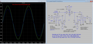
I wrongly put in last attachment here is the correction for 250V, 1k6 OT:
Pentode out 21V sg_ampl=12V, Thd 5.3% @27.5W Pout
UL out 16V sg_ampl =23.5V, Thd 1.38% @16W Pout
Triode out 21V sg_ampl=23.5V, Thd 1.37% @27.5W Pout
Hi Koonw,
Check your sim, r3 and r4 are different values (both should be 200), Pout for triode looks about twice as high as it should be, and the transformer as shown is 1.2k:8 (60H primary to 0.4H secondary). Also for THD should sim for more cycles and have a settling delay.
Bohrok2610 - peak anode dissipation exceeds the limit but average is under 20W over the full cycle.
peak anode dissipation exceeds the limit but average is under 20W over the full cycle.
You are correct. I've had a couple of E130L turn gassy so I'm a bit wary of the anode dissipation limit. Both Tungsram.
 .
.You save the file and then open with LTSpice, make sure it has .asc and not .txt extension.
I'll try it
Mind to elaborate why you've assigned gassyness with top cap tubes?
Btw, Tungsram from Hungary never was among the tube manufacturers with the best reputation in Europe
I'm referring to tubes with anode top caps. I'm assuming the seal between the glass and the top cap wire is more exposed to heat than if the seal is at the base. Well not only assuming as there are tubes that have additional cooling heatsinks on top caps (e.g. see YL1070/YL1071 datasheet). I have a bunch of NOS YL1070s and they tend to get really hot.
AFAIK Tungsram made E130Ls were sold under several brands (e.g. Siemens, Valvo, Amperex).
6N6P
I was planning on using 6N6P's for phase splitter & driver (maybe using one for each phase & another for driver), but I also have some 2C22's which would probably be overkill for a driver, I will have a look in my stash, as I thought I might have some 6N2P's.
I still can't open those files & I have LT Spice.
The grid current of either model has not effect unless you're dealing with small signal tube and operation point near zero bias. However some power tubes has very large grid current e.g 6c33cb and curve is only good from -2V. Some tube curves has small grid current curve at the left bottom e.g Russian 6N2P, grid can be included quite accurately.
The grid current in the model file is controlled by value of IGA, IGB and IGC which can be adjusted to match grid current curve. But Paint tool allows you to do repaint it by pasting the model files into "Model" and then "Update", this is how all my models are updated.
I was planning on using 6N6P's for phase splitter & driver (maybe using one for each phase & another for driver), but I also have some 2C22's which would probably be overkill for a driver, I will have a look in my stash, as I thought I might have some 6N2P's.
I still can't open those files & I have LT Spice.
E130L Philips
I have some Siemens, are these likely to be Tungsram? I also have just 2 Philips.
Not Valvo, as E130L was a Philips development.
Anyway, after the shutdown of West and Central European tube manufacturing plants in the mid of the 1970ies, they stamped anything on tube envelopes of East European provenance.
Best regards!
I have some Siemens, are these likely to be Tungsram? I also have just 2 Philips.
6n2p model with grid current model:I was planning on using 6N6P's for phase splitter & driver (maybe using one for each phase & another for driver), but I also have some 2C22's which would probably be overkill for a driver, I will have a look in my stash, as I thought I might have some 6N2P's.
I still can't open those files & I have LT Spice.
Vacuum Tube SPICE Models
You can download the entire tube model here:
https://www.diyaudio.com/forums/att...cuum-tube-spice-models-tubemodel_3-20_win-zip
How do you open the file? If you double click it, the asc file should be first associated with LTspice. What is error message?
I still can't open those files & I have LT Spice.
Can you use LT Spice in general ?
I was planning on using 6N6P's for phase splitter & driver
Do you mean "driver" as the first tube of the amplifier ?
Driver is usually the tube "driving" the output tube(s). The tube prior the phase inverter is called voltage amplifier.
- Status
- This old topic is closed. If you want to reopen this topic, contact a moderator using the "Report Post" button.
- Home
- Amplifiers
- Tubes / Valves
- E130L PP Power Amplifier