About 20W with a OPT Raa=4k.The topic is about a push-pull , so triode mode up to 250V what power will give ?
The TS (post#1) has an OPT with Raa=1k6 (= value from data sheet) and wants 50-60W.
So, without control grid current and other Raa, no triode.
Mona
Last edited:
About 20W with a OPT Raa=4k.
The TS (post#1) has an OPT with Raa=1k6 (= value from data sheet) and wants 50-60W.
So, without control grid current and other Raa, no triode.
Mona
Based on the E130L triode curves I showed in #74 you might get closer to 30W if you dare to venture into grid current territory.
Attachments
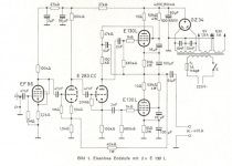
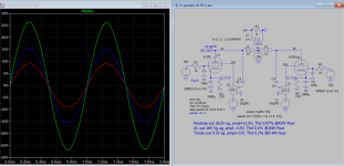
I don't have E130L tube model, but I used quite similar Svetlana's EL509 model to build a simulation of the full amplifier.
This is what I got:
Looks like a souped up Mullard 5-20.

max power limit is set by max cathode current and anode dissipation. Both will be reached and even exceeded without any grid current.
Not with E130L as triode and Raa=4k as in the examples above. Grid can become positive without exceeding anode dissipation or max cathode current.
4k might work in pentode at anode voltages far above 300V but you sure would not even come close to grid current region.
The E130L in triode is screen voltage limited so pp load of 4k is not the smartest thing to do. You would want a pp-load somewhere between 1.4-2.7k max.
Btw, at 250V Ua and -27,6V Ug the Ia would be closer to 140mA than 100mA. If you want 100mA you need a -Ug of 29V according to Philips datasheets.
The E130L in triode is screen voltage limited so pp load of 4k is not the smartest thing to do. You would want a pp-load somewhere between 1.4-2.7k max.
Btw, at 250V Ua and -27,6V Ug the Ia would be closer to 140mA than 100mA. If you want 100mA you need a -Ug of 29V according to Philips datasheets.
Last edited:
Not with E130L as triode and Raa=4k as in the examples above. Grid can become positive without exceeding anode dissipation or max cathode current.
sure, because your anode load is unreasonable high. If you for what ever reason want to run the E130L with grid current make sure to not accidently damage the grid and stay below 100mW g1 dissipation.
Last edited:
sure, because your anode load is unreasonable high. If you for what ever reason want to run the E130L with grid current make sure to not accidently damage the grid and stay below 100mW g1 dissipation.
So what would you use as load with E130L triode pp? Have you actually looked at the loadlines of E130L triode?
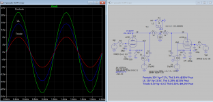
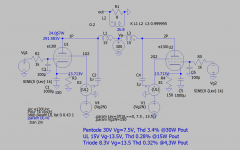
Pentode mode is quite sensitive, required only 7.5V to full power 30W and 3.2% distortion and output Z can be further lowered with CF. Here is my sim result with new model I just posted.
Attachments
Just read what I wrote all ready, transformer coupled pp with 250V Ub 1.4k for max power and good efficiency, up to 2k exchanging lower power for lower distortion.So what would you use as load with E130L triode pp?
I certainly have never drawn load lines based on curves your -Ug 27,6V and Ia 100mA biasing must be based on.
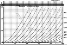
Get yourself triode curves from Philips for instance, make a few different models with
curve captor, check them against the tube manufactures published curves and use the one that comes closest.
At 250V and -Ug 27,6V you should get Ia close to 135mA +-5mA, not 100mA.
If you made your model by taking curves from a real tube the tube is probably worn out.
Just read what I wrote all ready, transformer coupled pp with 250V Ub 1.4k for max power and good efficiency, up to 2k exchanging lower power for lower distortion.
I certainly have never drawn load lines based on curves your -Ug 27,6V and Ia 100mA biasing must be based on.
Get yourself triode curves from Philips for instance, make a few different models with
curve captor, check them against the tube manufactures published curves and use the one that comes closest.
At 250V and -Ug 27,6V you should get Ia close to 135mA +-5mA, not 100mA.
If you made your model by taking curves from a real tube the tube is probably worn out.
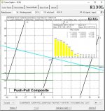
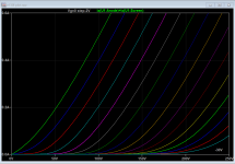
You apparently do not use loadlines with your amps. 4k load on 130L triode PP at 250V/100mA is actually quite reasonable if the goal is to have low distortion (see attachments). If you go to 2k load Ia needs to be lowered to about 50-60mA to not exceed anode dissipation limit. To use even lower 1.4k load does not make much sense. And please note that the loadlines in attachments are drawn from Philips datasheet.
Anyhow one of the main reasons to use E130L as triode is to have lower distortion. Negating this by trying to maximize output power with low Raa load is counterintuitive.
Attachments

If you want the sim asc let me know.
Please. I would like to compare with my results.
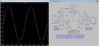
Two more snapshots, 250V and 300V HT version, hope these help in your project. If you want the sim asc let me know.
Thanks! Have you checked how well the triode curves from your model match the datasheet? At least the Vg-bias seems to be slightly off.
Two more snapshots, 250V and 300V HT version, hope these help in your project. If you want the sim asc let me know.
This looks really promising for what I'm building, I think that getting all PSU parameters correct on this is what will be challenging, the power transformers that I have are 2 x 0-275/330v toroids, I have gone belt & braces with these, I could probably have got away with one, but dual mono is the way i want to go.
- Status
- This old topic is closed. If you want to reopen this topic, contact a moderator using the "Report Post" button.
- Home
- Amplifiers
- Tubes / Valves
- E130L PP Power Amplifier