Hi All,
I'm just about to start a Push Pull Amp build using E130L Tubes, it will be a dual mono in one enclosure, output transformers are being custom built in Poland, input impedance 1.6k, phase splitters will be 6n6p's, grid v regs will be 0A2 gas tubes, the plan is for 50/60 watts into 4/8 ohms. This is my first Power Amp build, so any advice help on this would be appreciated. Everything I need is ordered, I've probably forgotten something.
I'm just about to start a Push Pull Amp build using E130L Tubes, it will be a dual mono in one enclosure, output transformers are being custom built in Poland, input impedance 1.6k, phase splitters will be 6n6p's, grid v regs will be 0A2 gas tubes, the plan is for 50/60 watts into 4/8 ohms. This is my first Power Amp build, so any advice help on this would be appreciated. Everything I need is ordered, I've probably forgotten something.
This is my first Power Amp build, so any advice help on this would be appreciated.
Your schematic would make it easier to comment.
He has six now i believe i send him two in the mail, and im doing the PCB design for the phase splitter power supply and bias arrangement.
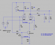
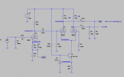
Currently we are thinking 6N6P phase splitter, long tailed pair with a two transistor current sink in the bottom, i really cant tell you the gain of this arrangement(16-20 i think) but some feedback may be needed to get the amp sensitivity right. As from what i understand he already has a preamp. According to the datasheet the E130L at 1K6 anode load and -17V negative need about 9VRMS to drive them to full output power.
Anode resistors would be around 18K with a total tail current of 20mA coupled by two 470nF caps into the 68K grid leaks connected to the bias servo.
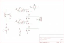
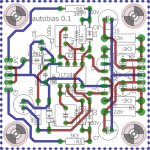
For the bias i was thinking of using the plug in modules ive made a PCB for to set the bias, see schematic and board attached, this will need a time delay to synchronize the application of B+ and bias to the tubes.
Currently we are thinking 6N6P phase splitter, long tailed pair with a two transistor current sink in the bottom, i really cant tell you the gain of this arrangement(16-20 i think) but some feedback may be needed to get the amp sensitivity right. As from what i understand he already has a preamp. According to the datasheet the E130L at 1K6 anode load and -17V negative need about 9VRMS to drive them to full output power.
Anode resistors would be around 18K with a total tail current of 20mA coupled by two 470nF caps into the 68K grid leaks connected to the bias servo.
For the bias i was thinking of using the plug in modules ive made a PCB for to set the bias, see schematic and board attached, this will need a time delay to synchronize the application of B+ and bias to the tubes.
Attachments
e130L
Yes Kay, I have some, 4 Siemens & a couple of Philips from Florick, al NOSDid you manage to get four E130L tubes?
Best regards!
Schematic
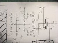
It's loosely designed using the Power Amp section of Martin Ecksteins design, with some changes highlighted by Florick, I haven't got everything together yet, I will sit down & design a proper schematic here, or at least scribble one out.Your schematic would make it easier to comment.
...output transformers are being custom built in Poland, input impedance 1.6k
That schematic shows a special output transformer with separate UL-winding. Are you going to have such opt ?
The 6N6P LTP with E130L output stage require some 2 Vrms input voltage to get full output power. If you are building hifi-amplifier, you will need at least 10 dB... global negative feedback. That is, the drive voltage from the preamp should be some 6 Vrms or more depending of the overal gain of the 6N6P/E130L-amplifier.
Concerning the 6N6P LTP, do you want to keep it full tube LTP or do accept solid state components as CCS (tail) ?
UL winding, it was offered at no extra cost, but I may not use it...
Then you are limited to pentode mode (with 150 Vdc to screen grids).
In this case you will need even more GNFB.
6V in is a lot, any suggestions are welcome..
Add one 6N6P as a voltage amplifier, ahead of the LTP.
Then you can add negative feedback easily.
6N6P
I ordered 8 more 6n6p's
Then you are limited to pentode mode (with 150 Vdc to screen grids).
In this case you will need even more GNFB.
Add one 6N6P as a voltage amplifier, ahead of the LTP.
Then you can add negative feedback easily.
I ordered 8 more 6n6p's
With only 250V max on G2 ( and typical 150V ) this is not a tube for ultralinear or triode mode in push-pull , even if you want . Maybe for single-ended .
So the best option is a stabilized G2 voltage , 150V or so .
Very similar with horizontal sweep tubes , wich have low voltage G2
So the best option is a stabilized G2 voltage , 150V or so .
Very similar with horizontal sweep tubes , wich have low voltage G2
Last edited:
The point where CCS is, i.e. at the cathodes of 6N6Ps has quite low impedance.
Then the demand for high dynamic impedance of the CCS does not exist.
Actually a LTP works fine even with a few kilo ohms resistor as a tail.
The idea of the CCS I suggested is that it has low noise and does not need negative supply voltage.
Then the demand for high dynamic impedance of the CCS does not exist.
Actually a LTP works fine even with a few kilo ohms resistor as a tail.
The idea of the CCS I suggested is that it has low noise and does not need negative supply voltage.
- Status
- This old topic is closed. If you want to reopen this topic, contact a moderator using the "Report Post" button.
- Home
- Amplifiers
- Tubes / Valves
- E130L PP Power Amplifier