You're right. Problem exists between chair and keyboard. Mea culpa.
It is Carbon Film. But then I don't understand it at all. I've read the film is 50-250nm thick. Which is 0.0002 of a 2mm diameter resistor. How can that film have any significant impact on the heat transfer? I would guess it would be negligible w.r.t. the ceramic core and even the protective coating thermal conductance.
It is Carbon Film. But then I don't understand it at all. I've read the film is 50-250nm thick. Which is 0.0002 of a 2mm diameter resistor. How can that film have any significant impact on the heat transfer? I would guess it would be negligible w.r.t. the ceramic core and even the protective coating thermal conductance.
The resistor type of choice for high power applications is wirewound.
Wirewound resistors do have higher inductance than film resistors.
However, in the 'tail' of a LTP (the cathodes) inductance won't matter. Actually, you could use an inductor there to act as a sort of current source. Of course a MOSFET can be made with much higher impedance to act as a *constant* current source, so all the better. But still, that goes to show you that inductance is not an issue there.
Have you read Morgan Jones "Valve Amplifiers"? These issues are covered in good detail there.
Valve Amplifiers - 4th Edition
Putting a resistor between the LTP kathodes and the constant current sink gives a sub optimal circuit in my opinion. If Vak is too high better diminish HT.The 10 Kohm CF resistor between the LTP's tail and the CCS drops some volts and also blocks the conduction of heat from the tube (via the wiring) to the CCS. Unwanted heat is the mortal enemy of all things electronic, especially SS. I took no prisoners.BTW, that resistor also slightly increases the net load the LTP tail works into.
Putting a resistor between the LTP kathodes and the constant current sink gives a sub optimal circuit in my opinion. If Vak is too high better diminish HT.
Why? It's not going to decrease impedance there, as long as the CCS has enough voltage to work with.
Well, my reasoning is that both active devices work opposed and the resistor takes a little of the voltage available from the CCS. The amount would equal R/CCS impedance. If the CCS impedance would be infinite there is no influence but if it would be say 200K, you loose 2,5% of its ability. Then there is valve capacitance to consider.
Last edited:

Very El Cheapo european solution. Nice.
Can you give any comment about the quality, especially of the OT? It seems good OT's are important and I'm willing to to spend some more where it matters.
Could you also elaborate a bit about the circuit changes you made? Why did you do them?
Can you give any comment about the quality, especially of the OT? It seems good OT's are important and I'm willing to to spend some more where it matters.
Could you also elaborate a bit about the circuit changes you made? Why did you do them?
If you want cheap the quality is not the top.They are German made, one can hope they didn't make a mess of itVery El Cheapo european solution. Nice.
Can you give any comment about the quality, especially of the OT? It seems good OT's are important and I'm willing to to spend some more where it matters.
.
With another supply transformer the circuit had to be adapted.After the rectifier nothing changed.The negative supply can come from the same transformer now and a more simple current source, constant voltage over the emitter resistor gives a constant current through the transistor.Could you also elaborate a bit about the circuit changes you made? Why did you do them?
The ECL85 resembles very much the 6AQ5 and 12AT7, no change there exept the decoupling and value of the cathode resistors of the output stage.
The value change is for a little less Pa, perhaps not needed but why push it.
And I don't like the common cathode resistor.If one tube starts pulling more current the cathode voltage goes up resulting in more negative Vgk for the other tube.With the more negative grid the current goes down making the unbalance even greater.
For the rest I changed some values more to my taste and higher input resistance.
Mona
Last edited:
Thanks Ketje for the explanation. I found more comments about the double cathode resistors.
In the mean time I've been researching, reading and simulating.
I think I need to switch to 6V6's, because they are much easier to come by, especially as matched pairs. I found in an old article that the UL tap should be at 20%. Any comment on that? Any transformers around that have that?
I also read part of this: Modern High-End Valve Amplifiers (E-book) - Elektor
His toroid transformers were mentioned before. Turns out his transformers were made a mile away from the highway I use to travel to my work (in the pre-corona age). They've moved a bit further away (20km) in the mean time. See attachment for one of their OT's.
The 35% tap is optimised for EL84. How important is the place of the tap? 40% seems quite common. Is this a reason, or a consideration, to switch to the Baby Huey?
Attachments
If you are recycling, as opposed to purchasing new, O/P "iron", even the total absence of ultra-linear (UL) taps is NBD.
By itself, "local" UL NFB usually yields an unacceptable damping factor and loop NFB of some kind, in addition, is required. Full pentode mode always requires loop NFB, for reasons of damping factor and linearity. However, open loop linearity in full pentode mode is maximized by regulating screen grid (g2) B+ at some fraction of anode B+. With regulated g2 B+, full pentode mode can easily be as good as UL mode. Regulated g2 B+ has a highly beneficial impact on the amount of irritating IM distortion generated.
The remarks I made here may be of some value in this project.
Witch amp, UL, triode global feedback often a question of taste, speakers environement.
On zelfbouwaudio.nl someone just finised a EL84 UL PP following (allmost) the schematic from DHTRob.Sounds very nice he said, but a little dull.Then he removed the overall feedback, the amp becomes to live, much better
So just build whatever and try it.No good ? start another, keeps you off the street
Mona
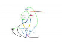
I put the (mono) audio part in DIYLC as a layout. I've done some layouts before using a turret board. I spent quite some time optimising those layouts. This time I might go with true point to point. Here's my starting point (see attachement). Not to scale yet.
Any general wiring advice wiring? Any general layout advice on point to point? Any specific advice for my (starting point) layout?
I can think of keeping the electrolytics cool, so the cathode bias resistor and capacitor should not be to close. I put the (power) filter cap close to where it's 'current is used', but it is very close to the hot tube (sockets).
Attachments
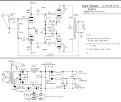
BYW96E is fast and causing less HF noise than say 1N4007 (in theory). I watch your solution to obtain a few dozen of volts for the negative supply. The (horizontal) 220uF/100V is catching any zener noise. Any use for a second tor to obtain higher CS impedance?Mona
The lower triode has a 1K stopper while the upper has 10K. Is that to cause a HF pole for GNF stability?
Attachments
Last edited:
I think that the impedance of the CCS is high enough with the big emitter resistance.Afterall in many cases they get away with a simple resistance.BYW96E is fast and causing less HF noise than say 1N4007 (in theory). I watch your solution to obtain a few dozen of volts for the negative supply. The (horizontal) 220uF/100V is catching any zener noise. Any use for a second tor to obtain higher CS impedance?
The lower triode has a 1K stopper while the upper has 10K. Is that to cause a HF pole for GNF stability?
Normaly 1k stopper is used but to cut of possible high frequency at the input, one can take advantage of the miller capactance and a higher stopper.
There could be something wrong with the cathode resistors in the final stage !
The triode curves for the ECL85 I have are looking suspicious after seeing those of a ECL82 but didn't found other (better) untill now.
Mona
Balance and linearity are dependent on the ccs impedance as far as I know. Can't give a hard answer if it is enough or not.
I've been playing with the grid stopper values in ltspice. Somehow they cause the overall high frequency response to increase. Van der Veen also shows some high frequency peak in his amp transfer function, but uses a grid stopper to crush that: the behavior I expect.
I will see if I can determine the bias resistors values myself or with your help. My guitar amps had fixed biassing, do I have something kinda new to learn.
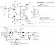
Then you put in the nearest standard value 680Ω as I proposed in post#80I checked the separate bias resistor values (for a 6V6). I have two methods that give roughly the same answer:
1) Just double the resistance as the current is halved: 2x330R = 660R
2) 14W/350V = 40mA. 350V, 40mA is on the -25V grid line. 25V/40mA = 625R
Mona
- Status
- This old topic is closed. If you want to reopen this topic, contact a moderator using the "Report Post" button.
- Home
- Amplifiers
- Tubes / Valves
- First stereo tube amp build advice