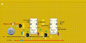
Oh I forgot to remove that resistor it was a leftover from the last version. Good catch. The ground from the relay will go to the terminal strip where the output caps will connect. From there a wire will connect to the xlr pins. So I won't have any signal line on the veroboard.
You could have the signals (coupling caps<>terminal strip<>XLR pins 2 and 3) go from the terminal strip to the relays. That would save a little bit of mess at the XLR's.
I'm drawing a blank on why the ground would need to jump to the terminal strip, though. AFAIK the ground could be shared by both relays, if it is reasonably closely connected to each XLR. Maybe fit a buss wire jumper between the XLR pin 1's, then tap the other required connections from about the midpoint of that -- that is, if you're willing to mess up the two stranded leads you already have soldered and are happy with.")
Once this is all working well, there's a fun little circuit to use the N.O. contacts of the relays, if you want to add a couple of LEDs to indicate 'Mute'. 2 transistors (BC547C's will work just great), 4 or 6 resistors, 1 each for 'L' and 'R'.
Cheers
I'm drawing a blank on why the ground would need to jump to the terminal strip, though. AFAIK the ground could be shared by both relays, if it is reasonably closely connected to each XLR. Maybe fit a buss wire jumper between the XLR pin 1's, then tap the other required connections from about the midpoint of that -- that is, if you're willing to mess up the two stranded leads you already have soldered and are happy with.
Once this is all working well, there's a fun little circuit to use the N.O. contacts of the relays, if you want to add a couple of LEDs to indicate 'Mute'. 2 transistors (BC547C's will work just great), 4 or 6 resistors, 1 each for 'L' and 'R'.
Cheers
Hey Rick,
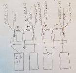
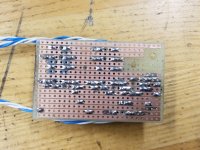
I've attached a drawing of what the terminal strip connections will look like. I've already started to solder wires and resistors on it.
On the preamp I have an unused wire at the chassis ground connection. I can attach this to the relay common strip. Once the relay fires there should no electrical connection between the ground and the xlr pins 1 and 2. I don't want to remove my grounding wires on the xlrs, unless absolutely necessary. Also I'm probably not going to include the 100r resistor unless absolutely necessary. I prefer not to have it in the signal path.
Thanks
Attachments
OK, NOW I see why you have a ground at the terminal strip. But I hope those ground terminals aren't just grounded by their mechanical connection to the chassis. They should have a line from the ground bus at the back panel.
The 100R is not absolutely necessary, but is considered *good practice*. It provides current limiting in the event of an inadvertent short, such as connector malfunction, or plugging into an un- or mis-grounded device, or other hard-to-predict mishaps. If it is a matter of mechanical convenience, it would be fine on the Vero board -- electrically the other side of the coupling capacitor. If you're concerned about sound quality impairment, there is none.
Regards
If you're talking about the Earth connection, where the wire from the IEC socket attaches, you should not use that... have an unused wire at the chassis ground connection.
The 100R is not absolutely necessary, but is considered *good practice*. It provides current limiting in the event of an inadvertent short, such as connector malfunction, or plugging into an un- or mis-grounded device, or other hard-to-predict mishaps. If it is a matter of mechanical convenience, it would be fine on the Vero board -- electrically the other side of the coupling capacitor. If you're concerned about sound quality impairment, there is none.
Regards
Hey Rick.
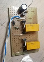
Thanks for the responses. I'm starting to moint the components on the veroboard. Your tip for layout really helped with keeping the layout smaller. Very slick thanks. I should be able to try out the circuit tomorrow.
All the grounds connect to the chassis at one point. This point is where I was going to get the ground from, yes the i.e.c. ground also connects there.
I'll give the 100r a bit more thought. Thanks for the input and explanation.
Some useful but to some annoying ground stuff:
Ground for audio, let's call it Audio GND. IEC ground, let's call it PE (protective earth). We agree on using different symbols for both to make it clear in drawings.
PE is for safety. The metal casing must be connected to it. If a mains voltage wire would come loose and touches the casing there will be a short circuit triggering the home circuit breaker (and no electrocution when we touch the casing because of the casing being connected to PE so 0V and the breaker tripping anyway). So the metal box is connected to PE everywhere and a loose wire will only harm the fuse/circuit breaker. Better them than us.
Theoretically we could just connect the casing to PE for safety and leave secondary side of transformers floating and have Audio GND floating. But ... we have a tube circuit with higher voltages than mains voltage and high DC voltages combined with a metal casing. So when such a B+ wire would come loose and touches the casing we also want fuses/breakers to protect us. Therefor we connect audio GND in a way to PE otherwise the high voltage circuit would be floating and a loose B+ wire touching the casing would not trigger the circuit breaker. Using a direct Audio GND/PE connection is asking for hum (the famous ground loops) but we do want safety. So we connect Audio GND to PE in "a way".
Audio GND is best being treated as a separate rail and kept tied together at one point and that point can be tied to PE via a 10 Ohm 5W resistor or other lifting technique. This way we have safety and we avoid hum as a ground loop is easily there when audio GND and PE are tied together certainly when done so in more devices in the setup. With the 10 Ohm resistors we have only one point where Audio GND and PE are connected with some resistance (but enough to guarantee the working of fuses/circuit breakers) and avoided a ground loop and get safety as a bonus. Of course we use isolated input connectors and output connectors.
Using a direct Audio GND/PE connection is asking for hum. Warning: using chassis as Audio GND is plain bad practice.
Last edited:
Hi JP,
Thanks for the explanation. Right now I have audio ground together and then going to the chassis grounding stud. The PE ground also goes to this grounding stud. I don't have any 10 ohm resistor on hand. Sounds like i could bring the audio ground to a terminal strip add a 10 ohm resister and then go to the chassis ground correct? I don't have any 10 ohm 5w resistors of course. Any type of resistor here?
Thanks for the explanation. Right now I have audio ground together and then going to the chassis grounding stud. The PE ground also goes to this grounding stud. I don't have any 10 ohm resistor on hand. Sounds like i could bring the audio ground to a terminal strip add a 10 ohm resister and then go to the chassis ground correct? I don't have any 10 ohm 5w resistors of course. Any type of resistor here?
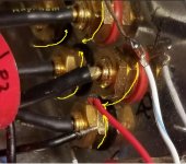
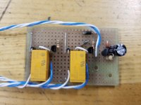
Have been studying your pic from post 140 and noticed something .. It's almost certainly not worth tearing out and re-doing, but if you have some other reason to redo the ground 'trunk' on the RCA's ..
You might try rotating the tabs on the jacks to produce a single, straight or approximately straight bus down the path between them. The 'U' shape you have now, in effect places a small-value inductor between the grounds of the same channel, each pair going down the row having a slightly higher inductance.
Don't worry about it unless some EMI-susceptibility comes up.
Those RCAs look really nice. Who makes those?
Cheers
Attachments
Last edited:
Hey Rick.
Hopefully it won't be an issue. I most likely won't be redoing those grounds.
I will be redoing the xlr grounding as you suggested. I had to redo the veroboard for the muting circuit and it no longer fit on the braket that it previously was mounted to so i had to make a new bracket. It's taking much longer than I expected. Those rcas are neutrik. I would not recommend them. They can't take any heat at all.
Thanks JP.
Rick
in an earlier post you mentioned not to rely on securing the large coupling caps by their leads as they could fatigue and break with vibration. How would you secure the caps to the chassis?
That's where I'm at now i have to connect the coupling caps to the new terminal post that then connects to the outputs (rcas xlrs) and muting relay
If you're sure you won't want to change them out some day, and it adheres to the outer wrap, a couple dots of hot glue or epoxy would do it.
I usually use a simple strap arrangement 'cause practically nothing I build is *for keeps*.
There's a company by the name of 'K & R', IIRC -- usually a small, dedicated display or an end cap, at your local hardware store or hobby shop. They sell brass, copper, and aluminum in various thicknesses, single packed, several in handy 4 x 10" panels; try a cm-wide-or-so strip of their 0,040" aluminum. I don't remember the alloy number, but it bends fairly easily without fatigue fracture, and holds a bend well-enough that it makes a good 'clamp'. A small hole near each end, just past the 90 degree bend, fits a machine screw to secure them to a flat surface. Probably two to a strap would be decently efficient. Just my two cents.
Regards
Last edited:
- Status
- This old topic is closed. If you want to reopen this topic, contact a moderator using the "Report Post" button.
- Home
- Amplifiers
- Tubes / Valves
- tube preamp makes rushing noise at speakers