OK, good -- on the Mouser.
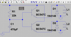
Here's the schematic - no great big deal.
Depending on your relay's current demands, one transistor may be adequate. But even all -C suffix devices may NOT have high enough current gain. The 22k resistor will have very little voltage across it as the relay(s) approach(es) full voltage, and therefore only providing a dabble of Base current for the transistor(s) -- 32uA unless I've booted the arithmetic. That's only 13,4mA even at the median beta of 420, which is higher than the lower half of the pool of -C devices -- by definition. Further complicating things, specs for beta are typically at a higher Vce, usually 10V or so. All BJTs are less conductive as the Vce drops; these will only have 1,3V across them if the supply is 6,3V, less if it droops.
Cheers
Attachments
Rick,
Thanks for taking the time out of your day to sketch up the
muting relay schematic. My parts order selection is coming along.
I was thinking of using this relay DS2Y-S-DC5V Panasonic Industrial Devices | Mouser Canada
should be good?
I'll order an extra to keep around if one goes bad.
Thanks for taking the time out of your day to sketch up the
muting relay schematic. My parts order selection is coming along.
I was thinking of using this relay DS2Y-S-DC5V Panasonic Industrial Devices | Mouser Canada
should be good?
I'll order an extra to keep around if one goes bad.
Yes, the DS2Y-S-DC5V from Panasonic should be fine, with a couple minor caveats:
- a little more current hungry than we'd prefer -- but we can work with it
- it is a Not Recommended For New Designs, which is a bad news / good news thing: If a replacement is ever needed, a 'direct' one may not be available; but the price is likely better.
Oh, and before I forget again: Practically any diode will work for the 1N4148's -- even most of the 1N400x family, or about any other 1A rectifier you might have handy.
Regards
What type of resistor are R12 and R16? Should definitely not be carbon comp...
You know your mono switch is shorting the inputs together? - not friendly to the source.
Just wondering what is a better option to get mono output.
I want to use it to setup the cartridge on my turntable.
Perhaps a 220R resistor from one volume wiper -- the source-side of C10 -- to the other. But I'd rather defer to the many wiser folks on this site for a proper answer to that question.
Also, 20V C10 needs to be a higher voltage. Since C9 comes from the great beyond, good practice would probably suggest a higher voltage rating for it, too.
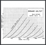
Would still like to persuade you to consider omitting, or substantially re-biasing, the 6SL7. As a Cathode Follower, its job should be to lower impedance. It can't do that with a 110k load; unless I mis-read the graph, that places the current in the low 300's uA range. Worse, being DC-coupled to the next stage forces it into yet another non-ideal operating point.
Stage by stage the impedance just keeps going higher and higher ..
Regards
Also, 20V C10 needs to be a higher voltage. Since C9 comes from the great beyond, good practice would probably suggest a higher voltage rating for it, too.
Would still like to persuade you to consider omitting, or substantially re-biasing, the 6SL7. As a Cathode Follower, its job should be to lower impedance. It can't do that with a 110k load; unless I mis-read the graph, that places the current in the low 300's uA range. Worse, being DC-coupled to the next stage forces it into yet another non-ideal operating point.
Stage by stage the impedance just keeps going higher and higher ..
Regards
Attachments
Last edited:
Hopefully someone chimes in on the mono switch.
Thanks for your input Rick. Once we sort out the bugs we can setttle on final circuit topology/values. At that time we can see much better without the various noises obscuring things on the instruments. That's my friends perspective.
Thanks for your input Rick. Once we sort out the bugs we can setttle on final circuit topology/values. At that time we can see much better without the various noises obscuring things on the instruments. That's my friends perspective.
Hey Guys,
Jean-Paul
I got my parts order in today.
So as a first step to quiet the noise you suggested to add a .1uf cap from the drain to ground of every fet.
So i added them, I only did one channel as a test.
Unfortunately it hasn't made any difference at all in the noise i still hear the same static sounding noise from both channels.
Gregas, .... 0.1 uf decoupling caps direct from the drain pins of the FETs to GND. .
All the steps necessary must be done. It is a combination of factors. There is a set of standard things to do to prevent circuits going wild. Decoupling power supply lines is a part of that. On itself it can today help and tomorrow it may not. No decoupling simply is below the minimum standard.
Normally circuits have been tested and proven to be stabile/not oscillating etc. Nowadays many first simulate to known what will happen. The cycle of building and trying out on the fly is not the way to do things properly so the first advice many experienced people will give are the standard things. They also had the issues and learned to tame circuits as anyone of us has built an amplifier that became an oscillator and vice versa.
When the circuit then still is not OK then it is a wrong design. The road to well performing circuits when you are not experienced is to build proven circuits first. The road of just building and paying attention to the parts themselves is not. It may also lead to frustration and time loss.
Last edited:
FYI: I am not the expert but just like you I had a bunch of non optimal circuits too. Like many of us the next step was to copy existing circuits and these were OK. Only after a certain time experience and theory may lead to own designs that are OK. Please note the "may". I recently designed a PSU and was completely astonished that it simply did not work. I had relied on my experience (and luck) and forgot a design rule I scrap such projects with a laugh on my face and start over again.
It is about topology and then quality of parts. It is an old fashioned way of thinking clashing with todays mind set but it is a proven way of doing things... if you care about quality, longevity, performance and such old fashioned things combined in a reasonable amount of time at reasonable costs that is....
I scrap such projects with a laugh on my face and start over again. It is about topology and then quality of parts. It is an old fashioned way of thinking clashing with todays mind set but it is a proven way of doing things... if you care about quality, longevity, performance and such old fashioned things combined in a reasonable amount of time at reasonable costs that is....
Last edited:
Hey Rick,
I was taking a closer look at the schematic for the muting circuit with the dual relay you drew up.
I was starting to think about how I was going to mount it on a strip board.
I noticed that you don't have the 1k resistor that Jean-Paul had in post #54
was that on purpose?
I was taking a closer look at the schematic for the muting circuit with the dual relay you drew up.
I was starting to think about how I was going to mount it on a strip board.
I noticed that you don't have the 1k resistor that Jean-Paul had in post #54
was that on purpose?
OK, good -- on the Mouser.
Here's the schematic - no great big deal.
Depending on your relay's current demands, one transistor may be adequate. But even all -C suffix devices may NOT have high enough current gain. The 22k resistor will have very little voltage across it as the relay(s) approach(es) full voltage, and therefore only providing a dabble of Base current for the transistor(s) -- 32uA unless I've booted the arithmetic. That's only 13,4mA even at the median beta of 420, which is higher than the lower half of the pool of -C devices -- by definition. Further complicating things, specs for beta are typically at a higher Vce, usually 10V or so. All BJTs are less conductive as the Vce drops; these will only have 1,3V across them if the supply is 6,3V, less if it droops.
Cheers
Not particularly -- but the 1k is considered good practice in a common-Emitter circuit. I usually leave it out on an Emitter-follower; it can be handy for trouble-shooting, though, since it allows a peek at the Base current, giving a better indication of how *turned on* the device is, than measuring the Vbe can.
Eager to hear how installing the 2k2 Gate-stoppers turns out, though.
Regards
Eager to hear how installing the 2k2 Gate-stoppers turns out, though.
Regards
I found this online regarding the transistor. It talks about that resistor. I should be able to install that 2.2k resistor along with the other parts on the strip board in the next 2 days. I will let you know.
BC547 as Switch
When a transistor is used as a switch it is operated in the Saturation and Cut-Off Region as explained above. As discussed a transistor will act as an Open switch during Forward Bias and as a Closed switch during Reverse Bias, this biasing can be achieved by supplying the required amount of current to the base pin. As mentioned the biasing current should maximum of 5mA. Anything more than 5mA will kill the Transistor; hence a resistor is always added in series with base pin. The value of this resistor (RB) can be calculated using below formulae.
RB = VBE / IB
Where, the value of VBE should be 5V for BC547 and the Base current (IB depends on the Collector current (IC). The value of IB should not exceed mA.Uh .. erm .. couple o' things:
1) it is not a switch in this circuit -- just a buffer providing current gain
2) please be skeptical of the website this came from --
- a) the Open/Closed switch / Forward/Reverse Bias sentence has it BACKwards
- b) not many transistors are *killed by anything more than 5mA*
- c) "VBE" is misused
- d) the formula is oversimplified and misleading
- e) they seem to have conflated reverse breakdown Vbe, and forward bias; the latter
will most likely measure around 600mV in a normally-operating circuit; but Collector
current will vary over 5 decades as Vbe ranges from 400 to 700mV
- f) if a BC547 ever measures 5V of forward bias, Base to Emitter, replace it promptly!
Regards
Last edited:
That is good news. As you see it can be both good and bad to rely on "standard" design techniques. Good because they solve things before they even occur, bad because they may lead to routine. Routine may lead to error. So essentially one always needs to be precise for best outcome.
Anyway, I am glad things are solved.
Anyway, I am glad things are solved.
 Good on ya' ! Great news !
Maybe when you get that Basie half worn out, you could post a pic or two? Bet the valve wizards on this forum will have a tip or two to address the hum problem, once they see some pictures.
IIRC you mentioned 4700uF's had replaced the 1000uF's in the filament supply? With only 0,1R for the 'R' in the CRC, that may still not be enough -- you have 1,5A of filaments to power. DC with too much ripple is actually worse than AC. It's a 120/100Hz sawtooth instead of an easily-compensated-for sine. And the huge charging spikes as the power transformer/bridge try to refill the caps generates far more EMI. Your whole circuit is very high impedance (more susceptible to *hum waves*).
No problem if you just want to enjoy it with the hum for a while -- I think everyone here understands.
If/when you are ready to tackle it, we'll need to start with AC voltage measurements on signal lines. But it'll take a more-capable-than-average meter to measure stuff at these impedances.
Cheers
Last edited:
Hey guys,
So the Preamp is with my friend he's going to trouble shoot the issues that it has including the hum. Rick I'll let him know about your concerns.
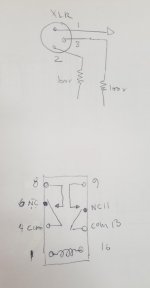
I'm trying to figure out the muting circuit relay connections at the moment.
Is there anyone who can explain how to connect the relay to the xlrs?
I've included a pic of the relay pinout/schematic .
So the Preamp is with my friend he's going to trouble shoot the issues that it has including the hum. Rick I'll let him know about your concerns.
I'm trying to figure out the muting circuit relay connections at the moment.
Is there anyone who can explain how to connect the relay to the xlrs?
I've included a pic of the relay pinout/schematic .
Attachments
- Status
- This old topic is closed. If you want to reopen this topic, contact a moderator using the "Report Post" button.
- Home
- Amplifiers
- Tubes / Valves
- tube preamp makes rushing noise at speakers