Hey guys
Actually two of my friends and I are working on a single ended integrated amplifier so we thought why not to write about it here in order to use group wisdom.
OPT and power transformers are made by a friend whos job is pretty good in building tube amplifiers:


he suggested to use 6n6/6H6 as input tube and two 6E5P Russian tubes do drive one GM70 but without any further details. here are PSU and amplifier schematic I got so far:


I'm not sure about using 6N6/6H6 and 6E5P. I may consider other tubes if I have access to. any idea is much appreciated.
Actually two of my friends and I are working on a single ended integrated amplifier so we thought why not to write about it here in order to use group wisdom.
OPT and power transformers are made by a friend whos job is pretty good in building tube amplifiers:
he suggested to use 6n6/6H6 as input tube and two 6E5P Russian tubes do drive one GM70 but without any further details. here are PSU and amplifier schematic I got so far:
I'm not sure about using 6N6/6H6 and 6E5P. I may consider other tubes if I have access to. any idea is much appreciated.
Last edited:
I can comment on the heater supplies, 20VAC rectified with a 50A diode block will give you more than 20VDC output, and the voltage will vary with the mains voltage.
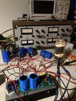
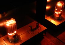
I have developed a heater regulator that is capable of glowing a GM70 as well, this may be just the thing for you. Dropout can be set very low, and if your heater windings are beefy. E.G. capable of 5A AC these will drop right in.
Attached picture is that of the module glowing a 813 10V 5A load.
As far as the high voltage supply goes, i need to look at that better to see if there are no drawing errors. I think you are using a GZ34 as the tube rectifier, correct?
Attachments
Free gerbers for boards
V4lve lover's free gerbers thread.
check post 11 for a nice board for your HT cap supply.
V4lve lover's free gerbers thread.
check post 11 for a nice board for your HT cap supply.
Hey guys
Actually two of my friends and I are working on a single ended integrated amplifier so we thought why not to write about it here in order to use group wisdom as we are not expert ...
I'm not sure about using 6N6/6H6 and 6E5P. I may consider other tubes if I have access to. any idea is much appreciated.
Very interesting project. One that I might try one day, if you get the kinks worked out here. 😁 Best wishes and please keep us informed of your progress.
I’m a novice with SE GM70, and had been eyeing designs on the internet, especially the Tsaar. See:
https://www.audio-creative.nl/wp-content/uploads/Tsaar-GM70-schema.jpg
I assume you have looked at other GM70 SE designs too.
One question - what is the primary impedance for your output transformer?
Originally Posted by dave123
I would not recommend SRPP. It has negative and positive feedback,if you do wan't feedback.")
Non Linear Behaviour of Shunt Regulated Push-Pull @ PAEng
Hey guys
Actually two of my friends and I are working on a single ended integrated amplifier so we thought why not to write about it here in order to use group wisdom as we are not expert in electronics.
OPT and power transformers are made by a friend whos job is pretty good in building tube amplifiers:
I would not recommend SRPP. It has negative and positive feedback,if you do wan't feedback.
Non Linear Behaviour of Shunt Regulated Push-Pull @ PAEng
Last edited:
We all know, between nice looking and nice sounding is a distance that equals earth to the moon. To wind a mediocre sounding transformer isn't too hard, one can do it mostly by learning on the internet in one day.Nice looking transformers, I need friends who can wind those too
To wind a supreme sounding transformer bears many hidden secrets thats mostly not free knowledge to achieve the easy way. I would just mention the anealing of the transformer core laminations and its process. With C-cores its different, but even C- cores sound different. In the end its a project with many unknown variables and when doing with no great circuit engineering knowledge, it could end anywhere. Maybe good or bad experience.
Attachments
Last edited:
Oh of course,I agree with you
Tube Output Transformer Concept / Pictures | TTRadio
Tube Output Transformer Concept / Pictures | TTRadio
I wouldn't recommend high freq. switching PSU for tube amps.A pair of Meanwell LRS-150-24 power supplies turned all the way down will happily heat your GM70s, especially since you are using fixed bias.
They are just a cheap and ready made solution, but they contaminate the whole amp with garbage frequencies that no one with a clear mind would prefer to have in such a unit.
I bought that regulator v4lve lover was showing in his post for that reason, he showed me some pretty awesome measurements on those. Now I just need to find some time in the lab at work because I want to see if I can find a meter that can show the actual noise floor instead of "less than 0.2-0.3 mV". Not that it matters anymore at that point but mostly out of curiosity
And well 20V toroids can be had for little money anyway
And well 20V toroids can be had for little money anyway
I wouldn't recommend high freq. switching PSU for tube amps.
They are just a cheap and ready made solution, but they contaminate the whole amp with garbage frequencies that no one with a clear mind would prefer to have in such a unit.
When I have used them and gone looking for those contaminants, I was unable to find them.
Rectangular pulses of switched sources have a wide spectrum and short duration, can penetrate wires and as radio interference, and cannot always be seen.
Not all interference from the 120vac power supply is visible or audible, but we connect filters to the 120vac input.
Not all interference from the 120vac power supply is visible or audible, but we connect filters to the 120vac input.
Last edited:
When I have used them and gone looking for those contaminants, I was unable to find them.
With a real mean well you might be in luck that they are quite decent and switch somewhere above the audio spectrum. We did run into that with an in house designed impedance analyser where the switcher we used for temperature control of the measurement cell was quite visible at specific frequencies. In the end it was fixable for us with a thick metal shield and shielded cables but I'm not sure that I would want to deal with that in a DHT amplifier
We have done so much, for so long, with so little,When I have used them and gone looking for those contaminants, I was unable to find them.
we are now being qualified to do anything with nothing
Last edited:
Rectangular pulses of switched sources have a wide spectrum and short duration, can penetrate wires and as radio interference, and cannot always be seen.
Not all interference from the 120vac power supply is visible or audible, but we connect filters to the 120vac input.
Yes, a mains→DC converter creates broadband noise that is not easy to control.
In my day job, I often have to add multiple-stage EMI filters to industrial equipment, just to reduce the SMPS noise enough to get the industrial product through the EMC standards tests.
This is not usually a problem for the DHT amplifier, if it does not use cathode bias, and it has been carefully wired.
The problem arises when there is a continuous ground connexion between the DHT amplifier and a DAC, or if the DAC is close enough to the amplifier to pick up EM interference. Broadband noise can degrade the DAC's analogue section, or the timing of input signals. It can be demodulated in current to voltage stages [I2V] if older opamps are used (before modern designs arrived with their EMI-hardening). Worst of all is EMI corruption of the Timing source - the crystal oscillator. If you have paid out extra for a low phase-noise oscillator (an excellent investment IME) the last thing you need is some clumsy power supply coming along and undoing the good work.
Think about why USB → I2S stages often come with a set of digital isolators - in order to break the USB ground connexion from noisy laptop PSU bricks.
This is the (main) reason I don't recommend mains→DC as the raw DC for use with my filament regulators. The problems arise in unexpected places.
Preamps or MC stages can also suffer, especially if NE5534 , AD797 or other older op-amps are in use.
The problems can be solved, more or less, if your design skills cover RF and EMC adequately - but the performance is usually still worse than if a good screened power toroid is used. And now that these are more widely available, and low cost (Antek AS series in the US, Canterbury Windings and Air-Link (audio grade) in the UK/Europe, Toroidy in Poland - there is little advantage from these converters.
Attachments
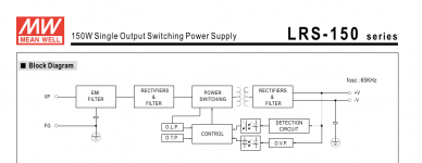
The pictures in the previous post were to illustrate a couple of other points.
In the block diagram, the capacitors from input to ground, and from output to ground will form a loop from the noisiest part of the converter (Raw mains, rectified and chopped up at the switching frequency) and ac-coupling it to the output negative which is connected to the filament. This is not a very happy place to ac-connect the filament to.
The other shot is of the Leakage current specification. This is the value of ac current that might flow from mains into the output. Needless to say, it's very noisy.
If you use cathode bias, the current flows through the cathode bypass cap, or the resistor.
Note also, that the converter's output cap is now in parallel with the amp's cathode bypass cap - which is not helpful.
I'm not trying to say it can't be done - but I do question whether the convenience is a good trade off for the performance, especially if remedial work is needed
To bring this high frequency switching noise within an analog tube amp is to deal with many problems. But people try to save a buck here and there. In the end, they want a great amp with minimal effort and cost without knowing, that those principles never have worked, especially in audio.
Reknown companies like Sony or Accuphase have shown the kind of effort it took to keep the digital noise outside of the analog circuits. Its not a small margin. I can audition it in my own system. When switching the digital gear on, analog sound becomes subtile worsening. Its very delicate to deal with that, isolation transformers can help.
I would never in this whole life come up with the idea to install such a digital contamination device in a pure analog unit to save five bucks or have a ready made solution. Because its not in the audio world. Maybe everyhwere else. And thats the problem. Because they were used so often, the AC becomes more and more contaminated with high freq. garbage. In the end, we need more to invest for pure AC supply. In a good (clean) environment this isn't necessary at all.
Last edited:
- Home
- Amplifiers
- Tubes / Valves
- GM70 SE amp project