If you mean filters made with common-mode chokes and "Y" Capacitors (line→safety earth), I think they are not necessary, and are liable to degrade the noise performance.
This kind of filter is produced to address some of the problems of mains→DC coverters, in order to meet the statutory EMC regulations (CISPR22 - EN55022 for IT gear for example). They are intended to reduce the portion of noise from mains→DC converters from getting back into the mains.
But if you have a transformer, with low PRIMARY→SECONDARY capacitance, the insertion loss (noise blocking) is already excellent, especially in the range 1Hz to 10MHz, where filtering requires very large components.
CM choke filtering often uses mH-region inductance values, and this reacts with capacitors to produces big resonance peaks in the impedance plot, often at quite low frequencies.
Meanwhile, the differential inductance of common-mode chokes is excited by the pulse currents of tube amp DC supplies, and generates noise of its own.
For mains isolation and noise control, a good quality mains trafo is needed. If you have one with an interwinding screen, there is no need for input filtering, other than an "X" cap across the Line-Neutral at the input.
This of course assumes that the DAC doesn't also contain a SMPS.The problem arises when there is a continuous ground connexion between the DHT amplifier and a DAC, or if the DAC is close enough to the amplifier to pick up EM interference.
Sorry, I forgot the main thing:
SE tube amp without NFB, in comparison with transistors amp, usually, but not always") , has a rapidly decaying spectrum of high-frequency harmonics, as well as THD corresponding THD of the ear:
, has a rapidly decaying spectrum of high-frequency harmonics, as well as THD corresponding THD of the ear:
https://citeseerx.ist.psu.edu/viewdoc/download?doi=10.1.1.497.2126&rep=rep1&type=pdf
Switching power supply deprives SE tube amp of the main advantage.
as well as diodes in the rectifier:
Diodes
SE tube amp without NFB, in comparison with transistors amp, usually, but not always
, has a rapidly decaying spectrum of high-frequency harmonics, as well as THD corresponding THD of the ear: https://citeseerx.ist.psu.edu/viewdoc/download?doi=10.1.1.497.2126&rep=rep1&type=pdf
Switching power supply deprives SE tube amp of the main advantage.
as well as diodes in the rectifier:
Diodes
Last edited:
I used the Meanwell supplies to heat my PP GM70s. Even after full turndown, there was still too much voltage so I burned off some with series resistance and then fed the fil via a CMC, no cap after. It was OK but later (now) I used a VCCS regulator after (Rod's would be another example) and it improved things quite a bit. Would a linear supply be better? I don't know, maybe, but I haven't the funds to find out and the amp sounds plenty good as is.
I would be concerned about the grid resistance for fixed bias in the GM70. 30K is recommended maximum for fixed bias. With 300k you might risk runaway. A 30k grid resistance would be hard for your driver and makes cap coupling very hard. You might need a rethink in this area.
I would be concerned about the grid resistance for fixed bias in the GM70. 30K is recommended maximum for fixed bias. With 300k you might risk runaway. A 30k grid resistance would be hard for your driver and makes cap coupling very hard. You might need a rethink in this area.
Can someone please help me to get GM70 tube datasheet?
A modern 1-page sheet:
https://frank.pocnet.net/sheets/084/g/GM70.pdf
I used the Meanwell supplies to heat my PP GM70s. Even after full turndown, there was still too much voltage so I burned off some with series resistance and then fed the fil via a CMC, no cap after. It was OK but later (now) I used a VCCS regulator after (Rod's would be another example) and it improved things quite a bit. Would a linear supply be better? I don't know, maybe, but I haven't the funds to find out and the amp sounds plenty good as is.
I would be concerned about the grid resistance for fixed bias in the GM70. 30K is recommended maximum for fixed bias. With 300k you might risk runaway. A 30k grid resistance would be hard for your driver and makes cap coupling very hard. You might need a rethink in this area.
Fixed bias via interstage transformer
I use SMPS (24V 4.5A) slightly modified, recapped and RCRC to get 20V. I am very happy with it and it works without issues 5 years now.
Can someone please help me to get GM70 tube datasheet?
Thank you..
I have one I can take a picture of if you can read Russian
The quality GM70 is different. I use GM70 without internal connections
??70 < ?? < ??????? < ????? < ???????? < ???????????? < AudioDB : ???? ?????? Audio
??70 < ?? < ??????? < ????? < ???????? < ???????????? < AudioDB : ???? ?????? Audio
Attachments
Hey better to blow up a 25 $/€ multimeter during experimentation and measure with a good one once the initial screwups have been fixed.
Do you happen to have a link to a thread/blog/website with more info on your build? I'm planning my own build with a friend and all inspiration is welcome
Do you happen to have a link to a thread/blog/website with more info on your build? I'm planning my own build with a friend and all inspiration is welcome
I blew up a few $25 multimeters so I keep aside good multimeters.
Unfortunately, I don't have anything on the internet except a small video.
Picture 002 - YouTube
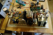
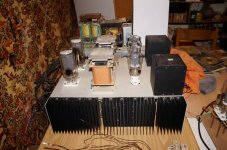
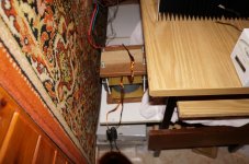
I adhere to a block design,therefore I am not drawing a complete schematics, but only schematics of individual blocks,and I stabilize all voltages with voltage regulator, so my filament and bias transformer has 102 pins (from memory).Voltage regulator of
1050V,300V,150V,-100V,-60,10v+10V,2.5V+2.5V...etc.Power supply weight about 45kg,amplifier 20kg and OPT 2 x 12kg.
Unfortunately, I don't have anything on the internet except a small video.
Picture 002 - YouTube
I adhere to a block design,therefore I am not drawing a complete schematics, but only schematics of individual blocks,and I stabilize all voltages with voltage regulator, so my filament and bias transformer has 102 pins (from memory).Voltage regulator of
1050V,300V,150V,-100V,-60,10v+10V,2.5V+2.5V...etc.Power supply weight about 45kg,amplifier 20kg and OPT 2 x 12kg.
Attachments
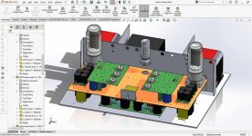
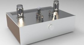
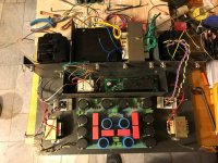
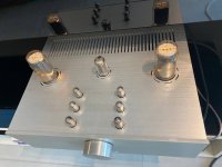
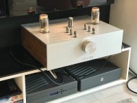
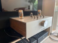
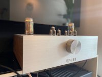
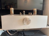
Hey guys. It's been a while since last post here. Actually, we managed to complete the amplifier after some prototypes and countless of hours tweaking and the result sound gorgeous. Teltuly stunning sound in our humble opinion.
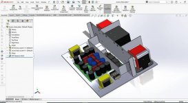
Here are some pictures of the final result. The chassis is made of 5mm CNC laser cut steel bent with high precision and welded. The outer layer is made of brushed aluminum and American white oak wood with Rubio Monocoat hard wax oil which brings out the nature of wood without adding anything to thickness.
I'm gonna share some thoughts about circuit design as soon as I have the time, hopefully before WWIII is waged!
Attachments
-
 IMG_20220619_203341_578.jpg116.8 KB · Views: 128
 -
 IMG_20220619_203339_218.jpg146.8 KB · Views: 129
 -
 IMG_20220619_203336_931.jpg61.5 KB · Views: 139
 -
 IMG_20220619_203335_056.jpg237.7 KB · Views: 140
 -
 IMG_20220619_203325_950.jpg106.5 KB · Views: 140
 -
 IMG_20220619_203318_504.jpg126.4 KB · Views: 138
 -
 IMG_20220619_203315_912.jpg65.1 KB · Views: 133
 -
 IMG_20220619_203313_646.jpg69.3 KB · Views: 123
 -
 IMG_20220619_203312_221.jpg80.4 KB · Views: 126
- Home
- Amplifiers
- Tubes / Valves
- GM70 SE amp project