I recently discovered this website: Triode / Pentode Loadline Simulator v.1.0 (20161216 www.trioda.com), and started playing with a 6SL7 driver tube for a single ended 6V6 amp.
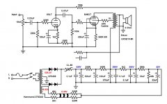
Here's the schematic:

And here's the load lines for the 6SL7:
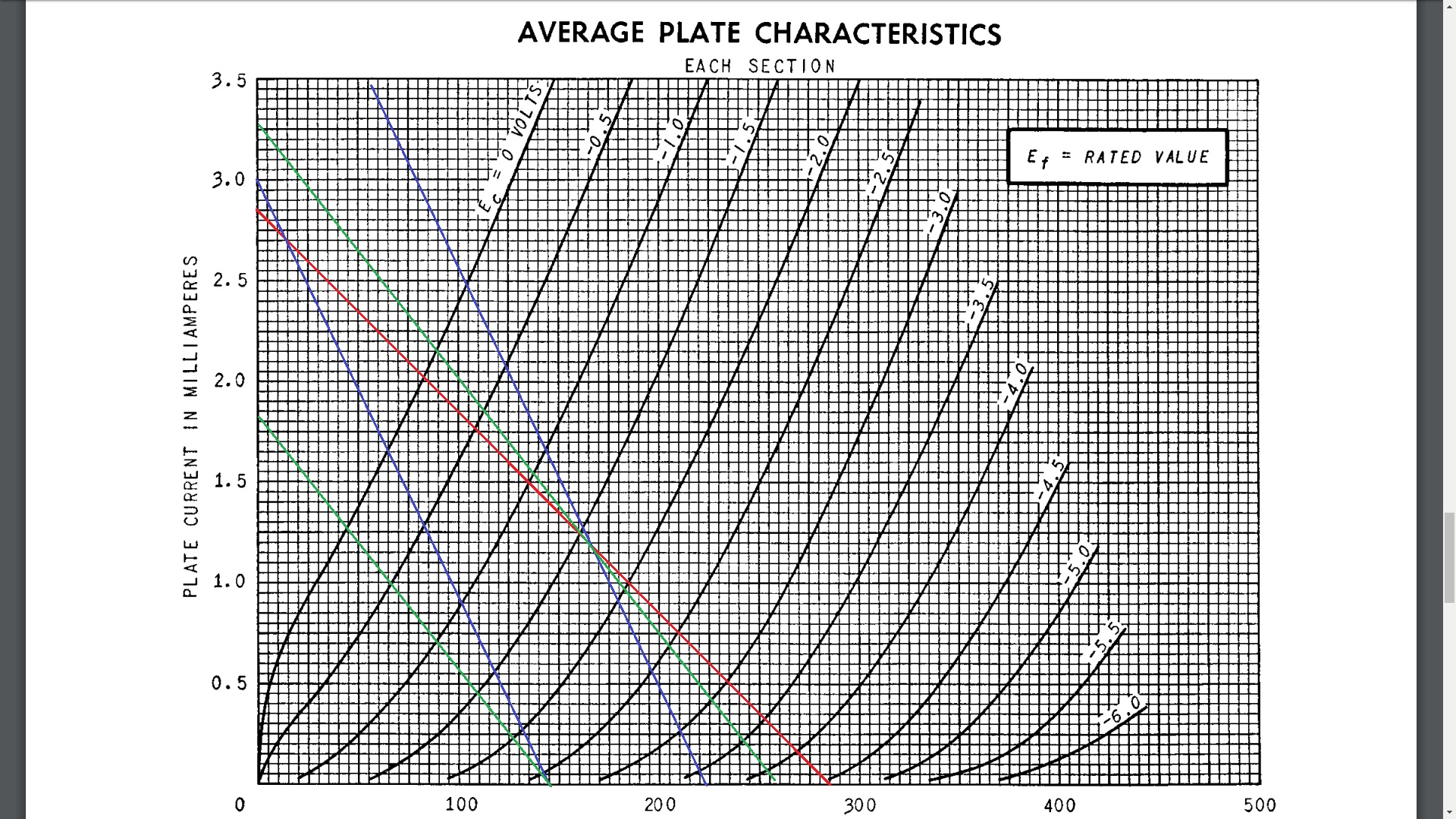
The red line is the DC load line, the blue is the AC load line for a 100k load, which is what I have. The green is for a 470k load, thrown in just for comparison.
The 6SL7 starts to clip with an input sine wave at 1.2V P-P scoped just after the 0.47uF coupling capacitor. It's just the top half. With the cathode at ~1.5V, I figured it should take a lot more than 1.2V P-P to clip the tube. The 6SL7 tube is a NOS RCA, well balanced and strong. I tried other tubes and the clipping remained the same. What am I missing? Am I misunderstanding something?
Oh, this is without NFB hooked up.
Here's the schematic:
And here's the load lines for the 6SL7:
The red line is the DC load line, the blue is the AC load line for a 100k load, which is what I have. The green is for a 470k load, thrown in just for comparison.
The 6SL7 starts to clip with an input sine wave at 1.2V P-P scoped just after the 0.47uF coupling capacitor. It's just the top half. With the cathode at ~1.5V, I figured it should take a lot more than 1.2V P-P to clip the tube. The 6SL7 tube is a NOS RCA, well balanced and strong. I tried other tubes and the clipping remained the same. What am I missing? Am I misunderstanding something?
Oh, this is without NFB hooked up.
Attachments
A 6V6GT needs something like 10 V input signal for full power. I think you are surely getting that before clipping, or? But if you would want to apply GNFB, I understand that you want more undistorted gain from the 6SL7.
As a rule of thumb, the value of the grid resistor of the next stage should be atleast 3 x higher than the value of the anode resistor (provided this is allowed per datasheet). With the 6V6GT with cathode bias, the maximum value for the grid resistor is 500K.
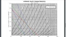
Here you can see what happens if you would higher the value of the grid resistor of the 6V6GT (and so higher the AC-load for the 6SL7):
As a rule of thumb, the value of the grid resistor of the next stage should be atleast 3 x higher than the value of the anode resistor (provided this is allowed per datasheet). With the 6V6GT with cathode bias, the maximum value for the grid resistor is 500K.
Here you can see what happens if you would higher the value of the grid resistor of the 6V6GT (and so higher the AC-load for the 6SL7):
Attachments
Is it not like audiowize already wrote in post #2?
The gain of the stage is about 34. The maximum output voltage (before crossing some distortion limit they use in the RCA Receiving Tube Manuals; see post #6) is 40.
34 x 1.2 = 40.8
Addition/correction: It's probably all true (go over 15 V output, than grid current of the 6V6GT; apply GNFB; etc.).
The gain of the stage is about 34. The maximum output voltage (before crossing some distortion limit they use in the RCA Receiving Tube Manuals; see post #6) is 40.
34 x 1.2 = 40.8
Addition/correction: It's probably all true (go over 15 V output, than grid current of the 6V6GT; apply GNFB; etc.).
Last edited:
So the whole story: Because I'm a knuckle dragging amateur from a non-engineering background, I approached this amps the "wrong" way. My goal was to drive the 6V6's to clipping, and then apply enough global NFB to tame everything down. The amp was built with the schematic as shown, and the voltages are all measured directly. I initially only scoped the output of the OT across a 8 ohm load resistor, and saw clipping. Using a 5k pot, I turned up the NFB until the clipping disappeared with a 2V P-P input signal at 1kHz. I swapped in a bunch of compensating capacitor until I got a nice square wave at 1kHz. I was feeling good about myself as the amp sounded pretty good, and the frequency response was nice and flat from 40Hz to 18kHz, right in line with specs of the output transformers. Of course, I couldn't leave things well enough alone and started poking around. I lifted the NFB and scoped right after the 0.47uF coupling cap just to make sure I was clipping the output tubes. The 6V6's were still in socket. That where I saw the asymmetrically clipped signals. Once I get home, I'll check the signal with a meter as suggested.
As I type this, and seeing PCL200's post above, I just realized that the clipped signal is at the positive lobe, and I'm probably looking at grid clipping. I'll scope the anode of the 6SL7 before the coupling capacitor and will report back after I get home.
As I type this, and seeing PCL200's post above, I just realized that the clipped signal is at the positive lobe, and I'm probably looking at grid clipping. I'll scope the anode of the 6SL7 before the coupling capacitor and will report back after I get home.
Most likely you'll see the same thing (plus DC component).I'll scope the anode of the 6SL7 before the coupling capacitor and will report back after I get home.
You'll have to disconnect the driver from the output stage completely to see the difference.
My goal was to drive the 6V6's to clipping, and then apply enough global NFB to tame everything down.
This is a little backwards. Start with output valve/output transformer information, set your target damping/power/THD, then evaluate how much feedback you'll need. This then helps determine what's adequate in the driver stage.
Do also be wary that lots of feedback around a series feed output transformer will make for an amplifier that's conditionally stable at best.
Yep, it was grid clipping. I lifted the 0.47uF coupling cap on the power tube side and tacked on a 100k resistor to ground. The 6SL7 took almost 4V P-P input to show some rounding on the top lobe of the sine wave.
I've read about this before, and that's why I said I did it the wrong way. I got as far as differential equations in college, but that was back in 1989. Now, the thought of doing serious math makes my head all swimmy.
There's not much negative feedback, just a hair over -5dB.
So much to learn. Better keep my mouth shut, my eyes and ears open, and keep on lurking.
Thanks everybody!
This is a little backwards. Start with output valve/output transformer information, set your target damping/power/THD, then evaluate how much feedback you'll need. This then helps determine what's adequate in the driver stage.
Do also be wary that lots of feedback around a series feed output transformer will make for an amplifier that's conditionally stable at best.
I've read about this before, and that's why I said I did it the wrong way.
I got as far as differential equations in college, but that was back in 1989. Now, the thought of doing serious math makes my head all swimmy.There's not much negative feedback, just a hair over -5dB.
So much to learn. Better keep my mouth shut, my eyes and ears open, and keep on lurking.
Thanks everybody!
- Status
- This old topic is closed. If you want to reopen this topic, contact a moderator using the "Report Post" button.
- Home
- Amplifiers
- Tubes / Valves
- 6SL7 driver clipping