Hi,
I had a coupon on ebay last month, plus a coupon from a local toroidal supplier, so I bought this cheap amp kit with chinese tubes 6P13P that are equivalent to russians 6P13S:
TUBO a Vuoto HiFi 6P13P Amplificatore classe A Single-Ended POWER AMP BOARD Kit fai da te | eBay

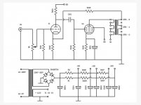
The schematic is attached.
I would like to improve it with the following:
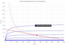
I would like to make them work at 270V B+ 50mA at idle and 5 kOhm primary impedance (see attached working point) to have around 5 Wrms.
Well, in theory, as I doubt the OPTs can supply that much power in the whole audio range...
Would you suggest to add an additional winding on the power trafo to have fixed bias?
Is there anything else you would suggest or do differently?
Thank you in advance,
Roberto
I had a coupon on ebay last month, plus a coupon from a local toroidal supplier, so I bought this cheap amp kit with chinese tubes 6P13P that are equivalent to russians 6P13S:
TUBO a Vuoto HiFi 6P13P Amplificatore classe A Single-Ended POWER AMP BOARD Kit fai da te | eBay
The schematic is attached.
I would like to improve it with the following:
- removing gnfb (have a bit more gain to apply other feedback methods)
- connecting R103 to the first 3rd of the OTP primary (shunt feedback)
- connect a 90/100V zener diode from cathode to screen (fixed screen-cathode voltage)
- add a screen resistor (safety)
- connect R105 and E101 to the 8 Ohm speaker tap. (cathode feedback)
I would like to make them work at 270V B+ 50mA at idle and 5 kOhm primary impedance (see attached working point) to have around 5 Wrms.
Well, in theory, as I doubt the OPTs can supply that much power in the whole audio range...
Would you suggest to add an additional winding on the power trafo to have fixed bias?
Is there anything else you would suggest or do differently?
Thank you in advance,
Roberto
Attachments
Last edited:
With these tiny output transformers I would not even consider pentode mode. Go for triode mode and expect very low output power.
They look a little bit like EL36 (not EL86!) which makes a pretty decent triode.
Requires a larger value cathode resistor than what is there now.
They look a little bit like EL36 (not EL86!) which makes a pretty decent triode.
Requires a larger value cathode resistor than what is there now.
Thanks, I've seen they are very small indeed. I've considered to be a possible area of future upgrades.With these tiny output transformers I would not even consider pentode mode.
At the end I'll pay it around 120 € PT included, I can invest something into it.
Thanks for the correctio, I see here they seem very good: https://www.diyparadiso.com/proj/amps/se/845sk light se/el36pentode_as_triode_v2.pdfGo for triode mode and expect very low output power. They look a little bit like EL36 (not EL86!) which makes a pretty decent triode.
I've seen the cathode voltage is way higher.Requires a larger value cathode resistor than what is there now.
I've seen this triode-connected design from a thread about PL36 tubes:
PL36 (triode) SE
But I'm not sure the triode driver in this case will be able to swing the output tubes to full power. Some simulations are needed.
PL36 (triode) SE
But I'm not sure the triode driver in this case will be able to swing the output tubes to full power. Some simulations are needed.
The 6P13S tube only resembles the EL36 in appearance, but differs significantly from it. While the 6P13S works well and stably with the UG2 ~ 400V power supply in the pentode junction, the EL36 tube works stably with half the UG2 ~ 200V maximum voltage. The Russian replacement for the EL36 is actually the 6P31S, so the similar name often leads to confusion.
I found what looks like the same output transformers in a Chinese kit using a FU32 (832B) where each tetrode is configured in single ended with 250V anode voltage and 50mA quiescent current. They are built following a inexpensive power transformer template; several identical primary and secondary winding sections are independently carried out on the contacts. It let me think about testing alternate series / parallel connections to get a lower primary impedence, as required by some output tubes.
Thank you for the clarification davorin!The Russian replacement for the EL36 is actually the 6P31S, so the similar name often leads to confusion.
They are built following a inexpensive power transformer template; several identical primary and secondary winding sections are independently carried out on the contacts.
This is what I've found:
Code:
1. Power: 3W

2. Frequency Response: 20z-30KHz (-2dB)

3. Core Specifications: EI48X24, core section X24MM

5. Primary Impedance: 5.5K Ω,

6. Secondary: 0-4-6-8 Ω and UV level meter use

7. Primary Inductance: 11H

8. Primary resistance: 278Ω

9. The primary current: 70MA

10. Grade resistance: 2.3 Ω
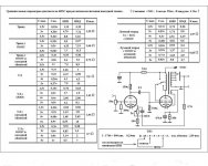
11. Weight: 0.6kg / pcsI've found this interesting page. Not related to the 6P13C but a comparison between different kind of feedback in SE amps.
триод = Triode
OOOC = Voltage negative feedback
катодная обмотка = Cathode winding feedback
ул = Ultralinear
тетрод = Tetrode
вход = Input
выход = Output
I still miss the 4th and 5th column, but I think one is THD.
триод = Triode
OOOC = Voltage negative feedback
катодная обмотка = Cathode winding feedback
ул = Ultralinear
тетрод = Tetrode
вход = Input
выход = Output
I still miss the 4th and 5th column, but I think one is THD.
Attachments
Last edited:
Member
Joined 2009
Paid Member
With these tiny output transformers I would not even consider pentode mode. Go for triode mode and expect very low output power.
They look a little bit like EL36 (not EL86!) which makes a pretty decent triode.
Requires a larger value cathode resistor than what is there now.
I wonder if there would be unintended consequences in triode mode from hum sine at least in Pentode the screen has additional RC filtering ?
It maybe instructive to first build the amp as intended, before changing it as then you will at least know how the designer heard it.

zintolo,
In your Post # 1, the schematic you posted has a very common error.
The order of tube elements from the bottom up is:
Filament (only when it is drawn in; otherwise it is assumed)
Cathode
Control Grid
Screen Grid
Suppressor Grid Or Beam Plates.
The common error in so many schematics is that those 3 grids are not connected in the correct order.
The control grid is not connected to anything, wrong.
The Screen is connected to the driver signal via RC coupling, and is DC returned to ground through Rg.
The Suppressor/Beam former is connected to a circle 'air' but indicating as if it is the screen supply voltage.
But the Suppressor/Beam Former needs to be connected to the Cathode.
That is the error in your schematic.
This can be confusing to a DIY builder, because his tube amp he just built according to the incorrect schematic does not work.
(And he carefully built it according to the pin numbers on the tube data sheet).
Last edited:
Aren't the Chinese well known for being world champions in copy & pasting?I've read many feedback on different forums, and all seem to say that there's basically no design behind it, just a copy-paste of old designs.
Best regards!
But the Suppressor/Beam Former needs to be connected to the Cathode.
That is the error in your schematic.
Thank you very much for your suggestion 6A3sUMMER,
I really appreciate you interventions and explanations of what is obvious for your experienced person, and not so much for newbies.
In this case there's a pcb on which everything has to be mounted, so most probably due to the cheapness of the project (oriented to unexperienced people) nobody ever gave feedback to the seller that the schematic is not correct.
This can also be due to the fact that LTSpice has no suppressor grid on it, and so it's something that can be forgotten for one more reason.
Your comment made me think about this thread: a better pentode for less!
Do you think it can be beneficial to have positive voltage on g3 for this tube?
As for the cathode feedback, keeping as correct the 5.5 kOhm and 8 Ohm ratio (I will check it), the CFB would be: sqrt(5500/8) = 26
So around 4% CFB.
By now I'm oriented into shunt + cathode feedback, but I would like to add UL too, switchable.
I've just read your suggestion ( SE UL question screen tap? ) that a direct connection to the anode would be better, because taking the signal from the 33% tap means introducing other parameters into the feedback loop. I will follow your suggestion.
Thanks again!
Aren't the Chinese well known for being world champions in copy & pasting?
Best regards!
Thanks Kay, most of the time yes. At least this is what made them famous worldwide: cheap products like this one cannot have hundreds hours of R&D behind.
Then there are expensive products that have R&D and can be somewhat cheaper due to lower labour costs.
This amp drops in the first case, and that is exactly what I wanted to try: a cheap amp with octal base for output tubes and noval for preamp, with built-in cheap OPTs.
Depending on the output transformer, the leakage inductance from the 33% UL tap to the Plate tap may, or may not, be an issue, even at 20kHz.
But there is an advantage if you use a low resistance feedback resistor to the lower resistor of the split driver cathode resistor to ground.
A 33% tap is only 1/10th of the total primary impedance. The UL tap can easily drive a low impedance feedback circuit, versus the plate tap. With the plate tap, more power is taken from the output to the feedback resistor.
In most instances, none of the above would be noticeable in either measurement or listening.
Perhaps it might be slightly different when reproducing a 5kHz or 10kHz square wave that had a fast enough rise time to have 50kHz of bandwidth.
But our loudspeakers and ears typically do not work at 25, 30, 35, 45, and 50kHz, the odd harmonics of those square waves.
A poor UL output transformer could be a problem.
But if you build a UL vacuum tube amp, be sure to use at least a medium quality output transformer.
Just generalizations:
A Triode or Triode wired Pentode/Beam Power tube can drive a poor output transformer (and even with a Triode you give up some sound quality). You will not always use negative feedback.
Pentode/Beam Power mode needs lots of negative feedback, which can make using a poor transformer difficult.
UL Pentode/Beam Power mode can sometimes get away without using negative feedback; that is quite a stretch, but it not only depends on the quality of the output transformer, but requires a higher impedance primary to work well that way. And, it might also be dependent on the loudspeaker it will be used with.
A long time ago, I have used Cathode feedback from the 16 Ohm tap.
The amount of the feedback is typically not very much; but that is good, because there is also the issue of leakage inductance, this time from the primary to the output tap.
Again, usually not a problem.
Any kind of negative feedback that includes the output tap can improve some things.
But it can also make things like lamination saturation worse.
Free Lunches? Where?
But all this indicates to us to use a good quality transformer.
Last edited:
So your suggestion would be: being sure that those small OPTs are far from optimal (just to use an euphemism) go pentode or triode, not UL.A poor UL output transformer could be a problem.
Because the internal impedance of the triode(/wired) tube is low, so can drive correctly even poor OPTs, I think. What do you mean by "with a Triode you give up some sound quality"?A Triode or Triode wired Pentode/Beam Power tube can drive a poor output transformer (and even with a Triode you give up some sound quality). You will not always use negative feedback.
I read few days ago you talking about this issue with feedback, that is one of the reasons why I would like to avoid it.Pentode/Beam Power mode needs lots of negative feedback, which can make using a poor transformer difficult.
Ok, so in this case, at least as a first step without upgrading the OPTs, it must be avoided.UL Pentode/Beam Power mode can sometimes get away without using negative feedback; that is quite a stretch, but it not only depends on the quality of the output transformer, but requires a higher impedance primary to work well that way. And, it might also be dependent on the loudspeaker it will be used with.
I've used it in a push pull, grounding the 4 Ohm tap and connecting the cathodes to 0 and 16 Ohm taps (even if not optimal, because the Rds of the two sides is different). I would like to apply this 4% here with the 8 Ohm tap.A long time ago, I have used Cathode feedback from the 16 Ohm tap. The amount of the feedback is typically not very much; but that is good, because there is also the issue of leakage inductance, this time from the primary to the output tap. Again, usually not a problem.
I will give it a try as cathode feedback together with shunt feedback anode to g1. I will post an updated schematic to make things clearer.Any kind of negative feedback that includes the output tap can improve some things. But it can also make things like lamination saturation worse.
and that is not the case as it is now, from the reviews I've seen online.But all this indicates to us to use a good quality transformer.
- Status
- This old topic is closed. If you want to reopen this topic, contact a moderator using the "Report Post" button.
- Home
- Amplifiers
- Tubes / Valves
- 6P13S SE cheap amp: improvement suggestions