It is a form of Schade negative feedback.
Usually Schade negative feedback circuits have a separate driver plate resistor that is connected to B+, and a second resistor from the output tube plate to the driver plate (the negative feedback resistor).
But sometimes it is done with a single resistor that serves dual duty . . .
Driver plate load, and negative feedback.
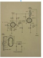
In your schematic, the feedback resistor came from the output tube UL tap.
Suppose the UL tap is 40%.
That would mean it is the same as taking it from the plate, except tor two things:
1. The amount of the negative feedback is reduced by 40% of using 100% of the output tube plate signal (8 dB less negative feedback than output tube plate feedback). The actual total negative feedback is dependent on the other circuit parameters.
Suppose that taking the feedback from the output tube plate, the total negative feedback was 18 dB. Then with everything else being equal, taking the feedback from the the 40% UL tap, the total negative feedback would be 10 dB.
2. The 40% signal from the UL tap might not perfectly follow the output tube plate signal.
That is because of the imperfect coupling of the 60% additional winding from the UL tap to the output tube plate. (due to leakage inductance from 40% to the other 60% windings).
The amount of the effect is dependent on the load of the 100 Ohms screen resistor in series with the screen impedance, versus the amount of the the leakage reactance. If it is of any measurable or noticeable effect, it is only at very high frequencies, due to the phase shift there.
Usually Schade negative feedback circuits have a separate driver plate resistor that is connected to B+, and a second resistor from the output tube plate to the driver plate (the negative feedback resistor).
But sometimes it is done with a single resistor that serves dual duty . . .
Driver plate load, and negative feedback.
In your schematic, the feedback resistor came from the output tube UL tap.
Suppose the UL tap is 40%.
That would mean it is the same as taking it from the plate, except tor two things:
1. The amount of the negative feedback is reduced by 40% of using 100% of the output tube plate signal (8 dB less negative feedback than output tube plate feedback). The actual total negative feedback is dependent on the other circuit parameters.
Suppose that taking the feedback from the output tube plate, the total negative feedback was 18 dB. Then with everything else being equal, taking the feedback from the the 40% UL tap, the total negative feedback would be 10 dB.
2. The 40% signal from the UL tap might not perfectly follow the output tube plate signal.
That is because of the imperfect coupling of the 60% additional winding from the UL tap to the output tube plate. (due to leakage inductance from 40% to the other 60% windings).
The amount of the effect is dependent on the load of the 100 Ohms screen resistor in series with the screen impedance, versus the amount of the the leakage reactance. If it is of any measurable or noticeable effect, it is only at very high frequencies, due to the phase shift there.
Last edited:
ok that sort of makes sense. So on the included circuit what is the amount of negative feedback applied?
It also looks like there is some local feedback on the input circuit.
Would this circuit work if the input tube was a triode? or doesn't it matter as its a type of global feedback?
just trying to understand thank you!
It also looks like there is some local feedback on the input circuit.
Would this circuit work if the input tube was a triode? or doesn't it matter as its a type of global feedback?
just trying to understand thank you!
I did some editing of my post #2, After you posted Post #3.
I am not a Schade negative feedback expert.
But this is what I observe in your schematic:
Pentodes have very high plate resistance, rp.
Usually a Pentode, but sometimes a Triode that has very high plate resistance, rp, is chosen for drivers in Schade feedback circuits.
Yes, the un-bypassed driver cathode is local negative feedback.
Un-bypassing the Pentode cathode resistor makes rp even higher.
And triode drivers are usually un-bypassed to raise their rp, to be able to properly use them for Schade feedback circuits.
So, the dominant impedances in the feedback circuit is the feedback resistor, 100k; and the g1 resistor 270k. All the other impedances are swamped out by those two resistors.
The negative feedback is strictly according to that resistor ratio.
(Well there is a little g1 to g2 Miller Effect capacitance, because the Screen is in UL mode)
I believe that is according to Rf and Ri feedback formulas, but do not quote me on that.
Look for RH84 amplifiers, and Sarris 807 amplifier on the web.
Sarris uses a 12AT7, un-bypassed, and parallel 807 outputs.
I am sure there are many who post on Tubes/Valves that have much more knowledge of Schade feedback circuits than I do.
I tried Schade feedback once, but I decided not to use that kind of feedback (on an amp I designed).
Now I am experimenting with feedback from the output tube plate,
back to a split resistor cathode circuit, with the feedback to the junction of the split, and with the top resistor bypassed by a cap across it.
Last edited:
so if that g1 is kept constant... all i would need to do is adjust the plate resistor of that driver pentode until i achieve the best gain, distortion, and sound for the amplifier?
i know that is in simple terms and may not be as easy as that.
This type feedback reduces input impedance correct?
i know that is in simple terms and may not be as easy as that.
This type feedback reduces input impedance correct?
The input impedance of the driver, 100k pot, and g1 is essentially constant.
The output impedance of the amplifier:
Since the tube is in UL, that makes the output impedance relatively medium to high Before applying global negative feedback.
But with global negative feedback, that lowers the output impedance according to the amount of feedback.
As to adjusting the feedback resistor, many things change.
And, one question is, what is paramount?
Gain, distortion, frequency response, max output before clipping?
You can not yank on just one thing and expect it to make all of those optimal.
As to sound, that depends on lots of things, including the loudspeaker you use (speaker impedance versus frequency, efficiency, damping requirements, etc.).
Are you getting ready to build something?
You have to decide what characteristics of your amp has to be, to work with the rest of your system.
Phono preamp only. Gain is important.
CD player only, Gain is less important.
Type(s) of music, how loud, room size, speakers, how complex to build and test, how expensive, first amplifier build, etc.
Once you build it, you may be pleased.
But once you get the bug, there may be other designs and builds that follow.
Last edited:
"thinking" of a SE UL 6v6 with 4x6v6 per channel. Just working on what to use as a driver tube.
Will use the Edcor 1.25K OPT. Will also have a Triode /UL switch on it.
6v6 will be run at 250vdv plate, 16v bias, 37mA each.
Not sure if i really need ANY feedback around that UL output stage... maybe a switchable one?
I need to have a bit of gain in this amp as i have a passive TVC for my volume.
Thanks!
For a quad of 6V6 tubes in single ended, purchase 6V6s that are fairly well matched.
And, I recommend enough space to use 4 individual self bias resistors, and 4 individual bypass caps for the output stages.
That way, there will not be 1 tube hogging more than its share of its current, and there will not be another tube "wimping out" with too little current.
That keeps the distortion down.
And checking the voltage across each individual self bias resistor tells how well each tube is doing, not just new, but 2 years later.
Go to eurotubes.com, and check out the JJ 6V6 (eurotubes in the Portland Oregon suburbs.
Eurotubes re-tests all the tubes they get from JJ in Slovakia.
A 1.25k to 8 Ohm tap has a fairly small step-down ratio, 12.5:1.
That helps the total gain you will get.
Make sure the output transformer is rated for 150mA quiescent DC current, or preferably at least 200mA.
- Status
- This old topic is closed. If you want to reopen this topic, contact a moderator using the "Report Post" button.
- Home
- Amplifiers
- Tubes / Valves
- SE UL question screen tap?