Hi Dorin, nice stuff.
However this set-up, made of a step-up transformer driven by a phase-inverter with small power triodes, is not suitable for class A2 or AB2. When power tubes enter positive grid the input impedance drops down to 1K or even less if you drive hard. With ratio you use will be even less....
At the very least you could do it with 1+1:1+1 but need to use a differential with small power tubes in the 10W plate dissipation class with as low as possible plate resistance, not a phase inverter!
You could use this phase inverter + choke & transformer to drive the driver stage. The simplest driver stage could be cathode follower or source follower on each leg directly coupled to the power tubes if have enough voltage swing.
Hi Dorin, nice stuff.
However this set-up, made of a step-up transformer driven by a phase-inverter with small power triodes, is not suitable for class A2 or AB2. When power tubes enter positive grid the input impedance drops down to 1K or even less if you drive hard. With ratio you use will be even less....
At the very least you could do it with 1+1:1+1 but need to use a differential with small power tubes in the 10W plate dissipation class with as low as possible plate resistance, not a phase inverter!
You could use this phase inverter + choke & transformer to drive the driver stage. The simplest driver stage could be cathode follower or source follower on each leg directly coupled to the power tubes if have enough voltage swing.
If you're speaking about "the third" phase invertor yes, I could have used a "1:1..." approach for my example but even with the given example one should keep in mind what part of A2 class operation want to explore, because the input impedance of the output tube(s) drops rapidly from, say, 500k to lower values but not instantly. "The third" is suitable for low power tubes up to 15-20W, where a classic Concertina/catodyne phase invertor has much higher THD and phase distorsion.
Yes Dorin, it doesn't drop instantly but is not a constant load with signal and a step-up ratio makes this worse because the driver stage sees it the square of turn ratio times smaller. Also, when grid current starts flowing in the secondary it will destabilize the bias, shifting up and down. Distortion in A2 or AB2 operation is proportional to the series resistance. For this reason in every datasheet where operation interstage is either recommended for both explained with examples, you will also find a maximum limit for both primary and secondary DC resistance. For tubes that don't require much positive drive 1:0.9+0.9, is usually about the max you will find but do not expect low distortion. Normally the output power is rated for 5% THD but that does not take into account the distortion of the driver stage.....
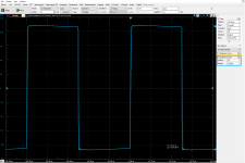
When the transition from 1 to 2 happens you will clearly it and will soon arrive to double digits if you go just a tiny bit further....like hard clipping
Regarding the phase splitters, I don't know an electronic phase splitter that likes rapidly changing or unbalanced loads. I have never seen a phase splitter driving a Class A2 or AB2 output stage, except the SE P transformer where the tube is only one and the degree of splitting is not affected (at least in the audio range for good transformers).
A properly made SE driver + SEP interstage will not suffer the output tubes if the ratio is good enough and will have perfect balance of the phases at least up to 50KHz regardless of the frequency response being flat or sloping down. If this does not happen it means that the transformer in not symmetrical enough. Of course if driving into A2 is a lot challenging for whatever reason (low impedance, high driving power and current etc..) nothing beats the source/cathode follower directly driving the power tube.
That's my experience.
When the transition from 1 to 2 happens you will clearly it and will soon arrive to double digits if you go just a tiny bit further....like hard clipping
Regarding the phase splitters, I don't know an electronic phase splitter that likes rapidly changing or unbalanced loads. I have never seen a phase splitter driving a Class A2 or AB2 output stage, except the SE
P transformer where the tube is only one and the degree of splitting is not affected (at least in the audio range for good transformers).A properly made SE driver + SE
P interstage will not suffer the output tubes if the ratio is good enough and will have perfect balance of the phases at least up to 50KHz regardless of the frequency response being flat or sloping down. If this does not happen it means that the transformer in not symmetrical enough. Of course if driving into A2 is a lot challenging for whatever reason (low impedance, high driving power and current etc..) nothing beats the source/cathode follower directly driving the power tube.That's my experience.
Yes Dorin, it doesn't drop instantly but is not a constant load with signal and a step-up ratio makes this worse because the driver stage sees it the square of turn ratio times smaller. Also, when grid current starts flowing in the secondary it will destabilize the bias, shifting up and down. Distortion in A2 or AB2 operation is proportional to the series resistance. For this reason in every datasheet where operation interstage is either recommended for both explained with examples, you will also find a maximum limit for both primary and secondary DC resistance. For tubes that don't require much positive drive 1:0.9+0.9, is usually about the max you will find but do not expect low distortion. Normally the output power is rated for 5% THD but that does not take into account the distortion of the driver stage.....
When the transition from 1 to 2 happens you will clearly it and will soon arrive to double digits if you go just a tiny bit further....like hard clipping
Regarding the phase splitters, I don't know an electronic phase splitter that likes rapidly changing or unbalanced loads. I have never seen a phase splitter driving a Class A2 or AB2 output stage, except the SE
A properly made SE driver + SE
That's my experience.
I'm not so happy focusing and insisting on how A2 class works, but thanks you reminded us all, as my circuits and xfmrs are not exclusively designed for this class of operation. As I have some trouble thinking about the tubes operating 100%, purely, in class A2 then for sure I don't recall seeing measurents at max power in A2... why? because they will be a nightmare from an electrical point of view.
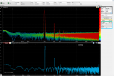
Top 5 classic transformerless phase splitters used worldwide exhibit THD between 1-5%, usually corrected by negative feedback and/or additional circuitry, this is where my simpler phase splitters can perform at least ten times lower THD w/o speaking of feedback
For the time beeing "Iron Schmitt" is a better alternative than classical SE
P xfmer, after counting pros and cons, of course.It's ok. I just saw some posts about it and some attempted to tell you more or less the same things.....
I don't use transformer coupling for class A2 or AB2 either. I prefer the DC coupled cathode follower after I have seen that there is no better way to do it.
Regarding tubes operating in pure class A2 there are a couple of fresh threads with measurements....distortion is low.
If I use an interstage it is for a classic circuit otherwise it's better to do without. It's just di9ffrent opinions.
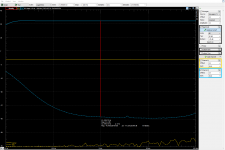
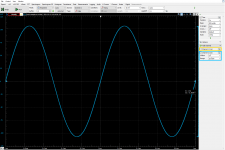
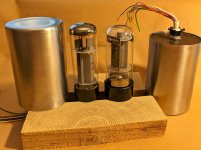
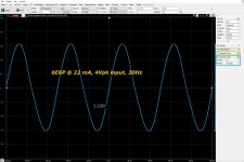
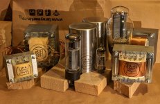
A recent variant of an interstage capable of "Iron Schmitt" circuit and much more, IS41SE20, wired in single ended and using a 6E6P tube as triode. I thought it will be interesting sharing a 20Hz, 300+Vpkk sine wave
Attachments
Last edited:
- Home
- Amplifiers
- Tubes / Valves
- Iron Schmitt, Concertissima & "the third" phase inverters :-)