Not sure I understand why 195Vdc is “the wrong number”. Your ‘08 schematic shows 194V drop across the plate resistors.I realized the 195v drop on the 6GK5 anodes was from a very old thread and 195v was the wrong number. I attempted to correct the voltage drop to get 102v on the anodes.
What is the first number? I assume it is the anode voltage after the resistor, that should be 102Vdc according to the schematic. So, clearly there is a bias issue because the tubes are not conducting equal currents. That was why I asked that you measure the voltage at the grids (and ground), to verify if there is any difference. The driven grid (connected to the volume control) behaves differently than the undriven one in each pair, yet they have common HV supply, as well as a common CCS at the cathodes. So, this is where I would look for a problem. This could point to grounding issues, solder or contact issues at the sockets, or mis-wiring of sockets or somewhere else.Assuming 6GK5 left pair is 1&2, right pair is 3&4. Measurements taken across 41.3k resistors
1) 265v drop = 11v 3) 262v drop = 14v
2) 224v drop = 52v 4) 230v drop = 46v
Please also measure the common cathode voltage for the two pair respectively. It appears that a second issue is with the bias point set by the CCS - neither tube in each pair is conducting sufficient current to get close to the 195V drop across the anode resistors. I think the -59V you get should work fine if the CCS current is adjuster properly.
What resistor value do you have in the power supply between A (6V6 B+) and B (6GK5 B+)? The drop you measure seems higher than expected with a 1k Ohm resistor, especially at the lower current your 6GK5s are presently drawing.
Good luck!
Sorry for asking for help and then dropping off the face of the earth. It's not a good time to be the lone IT guy at a school…Please also measure the common cathode voltage for the two pair respectively. It appears that a second issue is with the bias point set by the CCS - neither tube in each pair is conducting sufficient current to get close to the 195V drop across the anode resistors. I think the -59V you get should work fine if the CCS current is adjuster properly.
What resistor value do you have in the power supply between A (6V6 B+) and B (6GK5 B+)? The drop you measure seems higher than expected with a 1k Ohm resistor, especially at the lower current your 6GK5s are presently drawing.
Good luck!
So I checked the grid voltage on the 6GK5 pairs. At listening levels I got -.7v and -.4v. So it seems like I might be needing a new pot, because that seems quite unbalanced.
I checked out the CCS and it looks like I found the problem, but I don't know how to fix it. Previously, I only checked the voltage going into the 10M45S, I didn't think to check the voltage going out. With both pairs of 6GK5's installed the voltages on both 10M45S's are about -.35v. If I remove one pair of 6GK5's, the voltage going out of the 10M45 is instantly back up to -68v. The B+ is no longer unbalanced within the pair, I can bias to 102v as directed by the schematic. If I switch and install the other pair of 6GK5's, it behaves the same.
I don't know what would cause the CCS to behave like that

If you pull both tubes in the long tailed pair you will indeed measure the bias voltage at the cathode connection of the pair.
If you have 1K resistors available you could increase the value of the stopper resistor on the 10M45S 100R is a bit low, all the schematics ive seen use 1K
That buzz seems to be 120Hz to my ears, but i could be mistaken. Did you connect a source that may have a DC offset on its output? If so try to re do the measurements with no source.
I would include 1Meg from the pot wiper to ground, and veryfy that the bottom tube in the drawing indeed has some sort of ground connection between grid and ground.
Please post a hand drawn schematic of the bias supply as built, my gut feeling is that because its RC filtered the 6V6 bias is influenced by the current sources in such a way that they begin drawing excessive current and or the output stage becomes unbalanced.
That voltage doubler bias supply may be at fault here
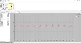
I simulated that voltage doubler bias supply, and this is what i got as hum on the capacitor. If you built it as drawn there could be some residual harmonics coming in through the 6V6 bias supply. Furthermore i cannot get the quoted -23V bias as per the schematic with this filter arrangement.
I simulated that voltage doubler bias supply, and this is what i got as hum on the capacitor. If you built it as drawn there could be some residual harmonics coming in through the 6V6 bias supply. Furthermore i cannot get the quoted -23V bias as per the schematic with this filter arrangement.
Attachments
Last edited:
- Status
- This old topic is closed. If you want to reopen this topic, contact a moderator using the "Report Post" button.