The control grid often is pretty close to the cathode, so I would think going over the limit might give flash-over/shorting.
Controlling negative voltage to the the grid via few 100kOhm resistor -if the grid shorted to the cathode- resulting only few-few ten mA current ... at kV negative voltage. Be forming the flash unbelievable. If the tube defective, anything is conceivable.
The control grid often is pretty close to the cathode, so I would think going over the limit might give flash-over/shorting.
Flash-over? Because of what? The grid shouldn't emit any electrons as a cold electrode, isn't it?
Because of the voltage difference combined with the closeness of the control grid to the cathode. But maybe it has to do (more?) with the maximum voltage differences between the pins. If the control grid goes negative, the difference with the positive pins (anode, screen grid) gets larger.
Last edited:
Controlling negative voltage to the the grid via few 100kOhm resistor -if the grid shorted to the cathode- resulting only few-few ten mA current ... at kV negative voltage. Be forming the flash unbelievable. If the tube defective, anything is conceivable.
There are other ways to connect the control grid than via a 100K resistor.
The control grid often is pretty close to the cathode, so I would think going over the limit might give flash-over/shorting.
I agree with Robert's assessment: it's probably the maximum voltage difference that can be applied between the grid and cathode before arcing might occur. Almost all tube datasheets show a maximum heater-to-cathode voltage rating for the same reason. There doesn't have to be any electron emission for arcing to occur between two electrodes if you apply a large enough voltage across them.
Last edited:
There are other ways to connect the control grid than via a 100K resistor.
Vacuum gap breakdown: 3 kV/mm in general!
Vacuum gap breakdown: 3 kV/mm in general!
Quoting a source for this claim would be helpful. But generalities rarely apply to specific situations anyway.
The reality is that the voltage required for arc-over depends on the distance between the electrodes. The closer the spacing, the less voltage that can be withstood before arcing occurs. Note that the maximum heater-to-cathode voltage rating for most dual triodes is in the 100 to 200 volt range. There is no reason to suspect that the maximum rating for the grid-to-cathode would be significantly higher than this. I personally would heed the datasheet specification; if it says 40 volts, I would believe that.
Last edited:
An article about cathode to control grid spacing dimensions.
But what do you think is the reason that so many datasheets state the maximum control grid to cathode voltage?
OK, Mullard article of the high gm PCC89 describe G-K spacing 50 micron, so -estimated- breakdown voltage is -150V.
The datasheet suggest not more than -50V.
This tube operates in 0...-3.5V Vg region.
If any application -at failure- put to grid more than tenfold or even forty times voltage, it's not "normal", it's poorly designed, bad construction.
Each well designed circuit use 20-50% greater negative power supply, than negative peek of grid swing, but not several times larger.
Each well designed circuit use 20-50% greater negative power supply, than negative peek of grid swing, but not several times larger.
Just to explain why I asked:
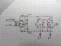
I'm playing with some hot logic circuits, so something complete different than amps. A negative supply is needed for that stuff. To keep the supply simple, I prefer a symmetric one, e.g. +/- 100V or so. See attached picture.
How ever, a symmetric supply seems to introduce some risks for the tubes involved in the logic circuits in case of unsymmetric rampup time (which may be the case because the negative supply has almost no load, just some MegaOhm-Resistors) or when R1 or R2 would fail (open circuit).
But as I have learned in this thread, this would not damage the tubes because the grid current would be strongly limited by the resistors.
So all is fine
")
all the best, Adrian
Attachments
Last edited:
Any "Bump" in the cathode coating, and any burrs on the metal work will cause a lower voltage to have corona breakdown (a different number than the flat to flat plane voltage breakdown numbers).
Example, there is a specially built 4-65A tube. It has a different part number stamped on it.
It has a higher voltage rating than the 4-65A tube.
The only two differences are:
The very careful removal of all burrs.
The higher price (when they were originally sold as new).
Example, there is a specially built 4-65A tube. It has a different part number stamped on it.
It has a higher voltage rating than the 4-65A tube.
The only two differences are:
The very careful removal of all burrs.
The higher price (when they were originally sold as new).
Refer to the Eimac tube manual that talks about the specialized version of the 4-65A.
It is the maximum plate voltage that is different, the other maximum voltages are the same.
The spacing from the plate connection of the tube is the same, from the top of the tube,
to the other pins at the bottom.
Or please read about Corona in space.
So what is one of the concerns when one space craft docks up to the space station?
Corona.
It may not be a perfect vacuum, but it is pretty good. Yes there is air that close to earth.
. . . Kind of like a vacuum tube.
Last edited:
- Status
- This old topic is closed. If you want to reopen this topic, contact a moderator using the "Report Post" button.
- Home
- Amplifiers
- Tubes / Valves
- physical reason for max. negative Gridvoltage?