This guy that is bothered by HUM, is in my opinion being too picky for using a damn old console amp and EXPECTING it to perform like some "high end" unit.
Maybe try putting a bottom metal cover on the thing to shield it better.
Mod the PS for better filtering... put shields on the input tubes....
Or just tell the louse to spend some money on a "high end" amp and shaddap.
Maybe try putting a bottom metal cover on the thing to shield it better.
Mod the PS for better filtering... put shields on the input tubes....
Or just tell the louse to spend some money on a "high end" amp and shaddap.
Would measuring it with the 5U4 unplugged give an indication whether the power transformer is radiating EMI to one output transformer more than the other?
Congrats on the 15 dB improvement by adding the 134 ohm resistor!")
Since the channels measured fairly similar on your bench -- before he tried it on his shelf, could there be an HVAC closet behind his stereo bookshelves?
Regards
Congrats on the 15 dB improvement by adding the 134 ohm resistor!
Since the channels measured fairly similar on your bench -- before he tried it on his shelf, could there be an HVAC closet behind his stereo bookshelves?
Regards
Last edited:
Can you duplicate the hum results in your own system? If you short the inputs do you still have the 2mv hum in one channel only? These tests will tell you if the owner of the amp could have a problem with a source related ground loop.
Does the hum sound like a 60hz sine wave or more like 120hz with a high freqency buzz? This can tell you if it is being picked up from the power supply or from induced 60hz hum pickup. Check the input wiring on the noisy channel. Is it properly shielded or twisted and run close to the chassis. Is the input wiring longer or running close to a power transformer or PS filter cap? Replacing a twisted pair with a shielded twisted pair should reduce hum pickup somewhat, and perhaps rerouting the wiring could also help.
It’s hard to guess what is going on without seeing it and hearing the problem.
Member
Joined 2009
Paid Member
If the outputs are in pentode mode then it’s not going to nearly as sensitive to the B+ ripple on the anode as will be to the supply to the screen grids. Perhaps try additional decoupling of the screens, current is lower there so the job is easier.
edit: I see screens have their own 300v supply which may already be well filtered but no schematic of the psu
edit: I see screens have their own 300v supply which may already be well filtered but no schematic of the psu
Last edited:
The coils are not aligned though. This should not be an issue.I'm just waiting to discover the 2mV channel is the one whose output transformer is in-line with the power transformer!
I had that same amp for a very long time and never noticed this behavior. The grounding is pretty abhorrent though, dealing with that may quiet things down a bit more, as would paying attention to heater routing.
I do agree though that this is an old console amp that doesn't exactly represent the pinnacle of tube amp performance.
I'm just waiting to discover the 2mV channel is the one whose output transformer is in-line with the power transformer!
Thanks!
I too, am concerned as you are about PT inducing hum into adjacent OT...
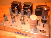
Per below chassis layout, L ch has audible no sig 'hum', R ch does not.
Applying different PCB designs to chassis layout-
Original was Chifi PP- condition existed,
Currently Audio Note- condition still exists,
Soon Dynaco ST-35 design new PCB...
If still persists,
Then will be looking into either shielding for PT, or reconfigure mounting position.
Process is fluid-
Jim
Attachments
Last edited:
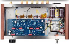
Per below-
Yellow square is where choke coil is mounted between filter caps. "R" & "L" (should be reversed- oops!) denote OT locations top of stainless steel chassis. Choke coil replaced original 75 ohm chassis mount- "X".
Blue outlines depict 7mm(+/-) PC board extension needed for subsequent designs...thoughts?
Jim
Attachments
Last edited:
Turn the amp off, remove the power cord.
Then use a DMM to measure the voltage on the B+ capacitors.
If there are no bleeder resistors on the B+, you need to install one (Safety First). Careful, you need to discharge the capacitors first.
Unsolder the Choke, and remove it from the amplifier.
Using wire that has very good high voltage insulation, wire the choke outside of the amplifier (2 wires).
Then mount a screw, nut, and ground lug on the choke mounting tab; and solder a wire from the ground lug to the amplifier ground connection (Safety First).
Or, if you do not connect the choke frame to ground, be sure to wrap the choke in plastic, and do not touch it (Safety First).
Now, turn on the amplifier, and see if the hum level is improved (lower).
That will test if the choke was introducing hum into the left channel output transformer.
If you want to put the choke back in the amplifier, at least turn it so that the orientation reduces the hum level as much as possible.
you need to use that screw, nut, ground lug and wire to keep the choke frame grounded when you are turning it for least hum.
You really should use Electrical Safety Gloves when doing this, or you may come into contact with some point of B+ in the amplifier (Safety First).
Please let me know if that fixes the hum.
There are more than one kind of "stainless" steel. Some are magnetic, some are not. If a magnet is attracted to the steel, then the magnetic fields of the power transformer and choke can be magnetically transmitted to the output transformers.
Most of my amplifiers have Aluminum chassis.
But I have one magnetic steel chassis. I use Aluminum spacers, and longer screws to mount the power transformer, choke, and output transformers about 1/4 inch away from the magnetic chassis.
Happy Listening!
Last edited:
If there are no bleeder resistors on the B+, you need to install one (Safety First).
Unsolder the Choke, and remove it from the amplifier.
Using wire that has very good high voltage insulation, wire the choke outside of the amplifier (2 wires).
Then mount a screw, nut, and ground lug on the choke mounting tab; and solder a wire from the ground lug to the amplifier ground connection (Safety First).
Or, if you do not connect the choke frame to ground, be sure to wrap the choke in plastic, and do not touch it (Safety First).
Now, turn on the amplifier, and see if the hum level is improved (lower).
That will test if the choke was introducing hum into the left channel output transformer.
If you want to put the choke back in the amplifier, at least turn it so that the orientation reduces the hum level as much as possible.
you need to use that screw, nut, ground lug and wire to keep the choke frame grounded when you are turning it for least hum.
You really should use Electrical Safety Gloves when doing this, or you may come into contact with some point of B+ in the amplifier (Safety First).
Please let me know if that fixes the hum.
There are more than one kind of "stainless" steel. Some are magnetic, some are not. If a magnet is attracted to the steel, then the magnetic fields of the power transformer and choke can be magnetically transmitted to the output transformers.
Most of my amplifiers have Aluminum chassis.
But I have one magnetic steel chassis. I use Aluminum spacers, and longer screws to mount the power transformer, choke, and output transformers about 1/4 inch away from the magnetic chassis.
Happy Listening!
4 takeaways-
1. Check if chassis is ferrous
2. Remote mount choke coil, then try grounding armature (B-) ...correct on the latter?
3. Use non ferrous spacers on PT & OT's if chassis is ferrous, to reduce/prevent noise
4. Report findings
Will update-
Thx,
Jim
ps. -and dont get shocked ;<)
Last edited:
My own tube amp, originally a Magnavox 93 Series amp (now highly modified by me), is laid out sensibly, has a choke, and has absolutely no hum.
Of course, it also has a "hum pot" in the filament line.
Need to post pics of mods to my amp. Dynaco ST-35 PC board retrofit design in process. Like those Z565's.. they get much love here.
What's your B+? UL or no? Cathode or grid bias?
Thx,
Jim
Is this a property of the final tube? (relocate it and remeasure).The 6BQ5 grids all measure about 4mV DC, except one, which is 30mV.
365V/300V are high supply voltages for type EL84, you might experience an insufficient cathode to heater isolation.
Need to post pics of mods to my amp. Dynaco ST-35 PC board retrofit design in process. Like those Z565's.. they get much love here.
What's your B+? UL or no? Cathode or grid bias?
Thx,
Jim
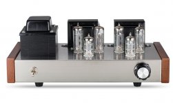
My amp is wired UL, the bias is the novel David Gillespie design (a form of fixed bias regulated to track any PS fluctuations) and the B+ to the OPT's is 300V.
Overall, the amp performs like one of those $5000 "designer amps".
I get a solid 17W/ch @4 ohms out of her with those Z565's.
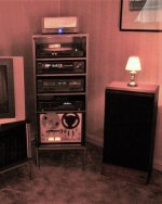
She sits on top of the equipment rack in the corner.
Attachments
Well, I fixed it.
After a little hair tearing, verifying the output stages performed identically with both grids shorted (6A3sUMMER's suggestion) I became convinced it's something to do with the driver tube for that side. With the rectifier out of its socket, I was getting 0.3mV on each speaker output; 0.1 with the amp off.
After verifying any ground potential difference were unmeasurable, I was out of ideas. Then it struck me this tube is the LAST on the heater string. Because this is a console amp, there was an extra filament winding just sitting there, unused. So I cut the connections and clipleaded it to this winding. Bravo! 0.5mV! So I twisted up a pair of solid core and - being careful to wire it up in the same phase - back to 1.2 mV, while the other channel is 0.5...
Shoot, so I reversed the phase, 1.1mV. Then I remembered WOT said "Of course, it also has a "hum pot" in the filament line". I dug out a pair of 68 Ohm 1/2 watt resistors and experimented where to connect the center tap to chassis. Turns out it didnt matter, so I connected them to the same solder blob as the Gnd of the 3 wire AC cord.
Fully expecting the other channel to now go up to 1.2mV, I happily found that both are sitting at 0.5mV, with inputs shorted, loaded into 8 Ohms resistive. The guy has the amp in his possession and we'll see if he cant hear anything this time.
Why did I do it? He seems interested. When I last visited, it was evident he couldnt identify the output transformers, nor the output tubes, as he asked about them - what they were. We all began somewhere similar. Plus, when you're retired, it's good to use the brain for something a little challenging electronics wise, even if it's a little POS amp like this one. It was amusing to see they actually bothered to bring the grid and cathode resistor ground for that tube all the way over to the input jacks - instead of just soldering to the chassis nearby - available on the next tab. Someone actually thought about the layout and connections.
Thanks for all the help, I'll post what the owner thinks when I find out.
Last edited:
He says he hears a hum difference between channels. I got the amp home and sure enough, one channel is at 0.5mV, the other at 1.1 (inputs shorted, 8 Ohm resistive load)
This thing is Haunted. I fail to understand how it can change like that; almost as if every time you turn it on, exhibits something different, just on that channel.
I tried powering the driver tube's heaters - on the bad channel - with a DC bench supply - even worse, going up to 2.5 mV. I havent tried a 6V battery yet...
The output tube G1 clip to ground test suggests it's coming from the screen / driver tube B+. Then why does the other channel perform so well - and consistently too?
I'm flabbergasted. I assume building a DC heater supply from that additional winding will do nothing for the issue. The driver tubes are 12AX7s with the heaters paralleled for 6V.
Any ideas? I'm fresh out -
Take a 1uf 400V cap, and connect it in parallel with the 150pF cap to ground (the grid of the concertina phase splitter to ground).
Then power up the amp, and see if there is hum.
When you grounded the output stages control grids, the hum went away, right?
Now, with the 1uF cap across the splitter grid, does the hum go away?
Depending on that answer, the cause is either the splitter, or the input stage and/or the B+ to that stage
Without going through all the postings in this thread, I will ask if you checked whether each output tube has the same cathode current.
If you did not check the current of each output tube, then put an individual 10 Ohm resistor from each cathode to the common self bias resistor and common bypass cap. With a DMM, measure the voltage across all four 10 Ohm cathode resistors.
Example, 0.4V across 10 Ohms = 40mA.
Even though the outputs are in pentode mode with a high plate resistance, if the currents are badly unbalanced, there will be some hum from the output stage.
I do not remember ever seeing any schematic for the power supply. That might be helpful for troubleshooting.
Last edited:
A recent Harman Kardon Citation amp that I had on the bench had old crappy loose tube sockets for all the driver tubes.
Hum and pops all over the damn place.
The only sure-fire remedy was replacing all 6 of them.
Oh, and hums?.... the HK amp required its bottom cover to make it totally silent.
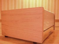
This guy's console amp has some crappy wooden board for a bottom?
Not gonna get rid of hum with that crap.
Hum and pops all over the damn place.
The only sure-fire remedy was replacing all 6 of them.
Oh, and hums?.... the HK amp required its bottom cover to make it totally silent.
This guy's console amp has some crappy wooden board for a bottom?
Not gonna get rid of hum with that crap.
- Status
- This old topic is closed. If you want to reopen this topic, contact a moderator using the "Report Post" button.
- Home
- Amplifiers
- Tubes / Valves
- Reasonable Tube amplifier Hum / Noise