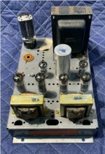
A neighborhood Audiophile brought me an ordinary vintage 6BQ5 / 12AX7 push pull amplifier, saying that he hears it has Hum, even with nothing connected to the inputs.
Having a quick look with my Fluke DMM, I measured 4mV RMS AC at the speaker terminals.
I measure 2V AC RMS on the 400V B+ - and single digit mV on the screen and 12AX7 B+. It uses a 5U4 for the rectifier and the power supply was designed to power a receiver, located in a different chassis. It has a large power transformer. No bottom metal panel; it's mounted onto a piece of wood.
I gave him some polyprop caps to replace the original coupling caps to the output tubes, as he told me he could solder. Inspecting, it appears he did this successfully. The 6BQ5 grids all measure about 4mV DC, except one, which is 30mV. (I believe this didnt change from what the original caps presented).
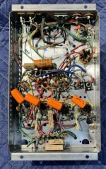
The AC cord is 3 wire, with the ground connected to the steel chassis. The grounding scheme of this amp is soldered directly to chassis, wherever was most convenient (i.e. no star or single point ground).
Are these values reasonable? What should a "good" reading be, in the circuit nodes I've mentioned? For a generic, vintage small tube amp operating correctly with no special power supply attributes, such as active regulation or choke filtering?
Thanks!
Having a quick look with my Fluke DMM, I measured 4mV RMS AC at the speaker terminals.
I measure 2V AC RMS on the 400V B+ - and single digit mV on the screen and 12AX7 B+. It uses a 5U4 for the rectifier and the power supply was designed to power a receiver, located in a different chassis. It has a large power transformer. No bottom metal panel; it's mounted onto a piece of wood.
I gave him some polyprop caps to replace the original coupling caps to the output tubes, as he told me he could solder. Inspecting, it appears he did this successfully. The 6BQ5 grids all measure about 4mV DC, except one, which is 30mV. (I believe this didnt change from what the original caps presented).
The AC cord is 3 wire, with the ground connected to the steel chassis. The grounding scheme of this amp is soldered directly to chassis, wherever was most convenient (i.e. no star or single point ground).
Are these values reasonable? What should a "good" reading be, in the circuit nodes I've mentioned? For a generic, vintage small tube amp operating correctly with no special power supply attributes, such as active regulation or choke filtering?
Thanks!
Can he post a schematic?
What speakers does he use?
Or does he use earphones?
Is there one or more (hum) ground loops?
I really work hard to get my amplifiers hum to be equal to, or less than 100uV.
I bet I could easily build a 12AX7 6BQ5 se amp to be less than 1mV hum (12 dB better than 4mV).
But I would use a B+ filter choke, pay attention to B+ ground loops, power transformer versus output transformer spacing and orientation (and the choke if any), and perhaps have to select a 12AX7 for low filament to cathode leakage.
No floating 12AX7 cathode with AC filaments, too much gain. With the separate screen B+, the 6BQ5 is in Beam Power mode, so it has lots of gain too.
And . . . No Steel chassis, Use aluminum.
Last edited:
Thanks for the replies to my issue,
There's a thread here from a couple years ago about restoring the same amp - NAD - Packard Bell DPA 30-4
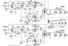
I obtained pictures of it from the internet and a close schematic from the above post, attached.
What I'd like to know is should I tell my neighbor "considering the construction, age and the fortune of decent preservation, it is what it is" or is there some way I can help out by making it a little bit better?
For example, I'm not about to refab the chassis in aluminum for him. Nor would I lift all the ground to chassis connections - but one - and rearrange every circuit ground into a single point, or star arrangement.
I realize if starting from scratch, one could create essentially the same thing with better noise performance. But what can I do with the "sow's ear" as presented to me?
Notice in the schematic the B+ is 377, while I'm reading ~400. Could I make use of that extra 20V to drop some across a resistor, deliberately placed between the 5U4 and 1st cap, to reduce the 2V of ripple I observed there? Should I go all out and buy a choke for the project and make a choke-input to the filter, instead of the resistor?
Or perhaps I do such and nothing changes - the 2V RMS of ripple on the B+ feeding the output transformers is NOT the cause and culprit. Perhaps a different - practically doable - circuit change is in order. But what? Provide each tube with its own cathode resistor / bypass cap? With my luck, I'd do all that and it'd make it worse...
Any thoughts - even if to advise of the impracticability of the situation, would be much appreciated. Thanks!
There's a thread here from a couple years ago about restoring the same amp - NAD - Packard Bell DPA 30-4
I obtained pictures of it from the internet and a close schematic from the above post, attached.
What I'd like to know is should I tell my neighbor "considering the construction, age and the fortune of decent preservation, it is what it is" or is there some way I can help out by making it a little bit better?
For example, I'm not about to refab the chassis in aluminum for him. Nor would I lift all the ground to chassis connections - but one - and rearrange every circuit ground into a single point, or star arrangement.
I realize if starting from scratch, one could create essentially the same thing with better noise performance. But what can I do with the "sow's ear" as presented to me?
Notice in the schematic the B+ is 377, while I'm reading ~400. Could I make use of that extra 20V to drop some across a resistor, deliberately placed between the 5U4 and 1st cap, to reduce the 2V of ripple I observed there? Should I go all out and buy a choke for the project and make a choke-input to the filter, instead of the resistor?
Or perhaps I do such and nothing changes - the 2V RMS of ripple on the B+ feeding the output transformers is NOT the cause and culprit. Perhaps a different - practically doable - circuit change is in order. But what? Provide each tube with its own cathode resistor / bypass cap? With my luck, I'd do all that and it'd make it worse...
Any thoughts - even if to advise of the impracticability of the situation, would be much appreciated. Thanks!
Attachments
Last edited:
As far as I can tell, you didn't replace any of the electrolytic capacitors. Start there. That's the first culprit. The big can and the cardboard wrapped guy.
+1
Old electrolytic capacitors is often the problem for various reasons on tube amplifiers I always change them even before I start an older amplifier.
Ground both grids of the 6BQ5 tubes.
Is the hum still there?
4 mV, or how much?
Then remove the wires grounding the grids.
(We are testing the B+ ripple, and the balance of the output tubes).
Connect a 1uF cap from the 7025 grid, pin 2 to ground.
Is the hum still there?
4 mV, or how much?
Careful, it has to have a high enough voltage rating (and discharge it with a resistor, when you remove it after the test).
If the hum is still there, there may be leakage from the AC powered filament to the 7025 cathode, pin 3.
You did not show the schematic for the power supply.
Does the rectifier tube test good? (unlikely, but one bad plate makes the hum worse).
Then there could be ground loops.
Many old consoles were not perfect.
They may have been open baffle, stiff woofers, and not had much response to low bass (and not much response to hum - from across the room).
Is the hum still there?
4 mV, or how much?
Then remove the wires grounding the grids.
(We are testing the B+ ripple, and the balance of the output tubes).
Connect a 1uF cap from the 7025 grid, pin 2 to ground.
Is the hum still there?
4 mV, or how much?
Careful, it has to have a high enough voltage rating (and discharge it with a resistor, when you remove it after the test).
If the hum is still there, there may be leakage from the AC powered filament to the 7025 cathode, pin 3.
You did not show the schematic for the power supply.
Does the rectifier tube test good? (unlikely, but one bad plate makes the hum worse).
Then there could be ground loops.
Many old consoles were not perfect.
They may have been open baffle, stiff woofers, and not had much response to low bass (and not much response to hum - from across the room).
Last edited:
This is not the best construction but you can't do much. The best practice would be to separate signal ground from protective earth (PE) to prevent ground loop.
A quick test what I always do is to plug in a shorting RCA plug in the L and R inputs. This shows the real hum of your amplifier. The next test is to remove the shorting plugs and listen to the loadspeakers. This will show the sensitivity to internal stray magnetic and electrical field. White noise may increase a bit, but hum should not.
You still might get hum if the amplifier is connected to some source, due to the potential ground loop that I mentioned earlier.
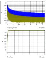
So I built some shorting plugs for the RCA inputs, allowing me to do a couple of experiments 6A3sUMMER suggested. Using my Fluke 87;
Channel A, at the speaker-connected outputs;
Unplugged (Unpowered) 0.3mV
AC on, Input Short 2.7mV
6BQ5 Grids Short 0.6mV
Channel B,
Unplugged (Unpowered) 0.2mV
AC on, Input Short 2.4mV
6BQ5 Grids Short 0.7mV
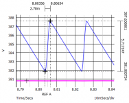
This is with B+ ripple @ 2.5V, on top of 400VDC.
The screens / driver B+ is 13mV on 352V.
The cathode bias is -13.92V @ 115 mA or nearly 29mA/tube
The original power supply has a large cap can with 2, 40uF 450V and two, 20u sections. The amp's power supply was arranged connecting the pair of 40uFs with the 20's, one section for the rectifier output, the other after a resistor drop, for the screens / driver tubes B+.
I thought I'd try dropping a voltage between the 20 and the 40uF sections following the rectifier tube...
Luckily, I had a 134 Ohm, 5W resistor on hand. That afforded a 15V drop between the sections and could easily handle the power diss. I connected the 20uF cap section to the rectifier tube. The resistor drops 15V to the 40uF section - and the rest of the amplifier.
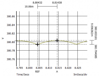
B+ ripple is now @ 1.18V, on top of 385VDC.
The screens / driver B+ is 10mV on 340V.
The cathode bias is -13.4V @ 100 mA or 25mA/tube
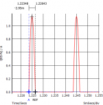
Now Both channel A and B report just 0.7mV RMS ripple, at each of the loaded outputs. ~0.5mV more than "off". These have got to be some small numbers, for a small, cheaply manufactured vintage tube amp. I have no idea what a "good" quality stereo tube amplifier would produce, regarding RMS output ripple/noise under short circuit input conditions.
Listening to John Klemmer's Waterwheels (it was late) out in the detached garage was sounding pretty good. Forget hearing any noise from this amp - at least for me - with tinnitus ringing. We'll see if my neighbor thinks so now. A good example of what you can do with just a DMM and a soldering iron - and a lucky resistor find!
Channel A, at the speaker-connected outputs;
Unplugged (Unpowered) 0.3mV
AC on, Input Short 2.7mV
6BQ5 Grids Short 0.6mV
Channel B,
Unplugged (Unpowered) 0.2mV
AC on, Input Short 2.4mV
6BQ5 Grids Short 0.7mV
This is with B+ ripple @ 2.5V, on top of 400VDC.
The screens / driver B+ is 13mV on 352V.
The cathode bias is -13.92V @ 115 mA or nearly 29mA/tube
The original power supply has a large cap can with 2, 40uF 450V and two, 20u sections. The amp's power supply was arranged connecting the pair of 40uFs with the 20's, one section for the rectifier output, the other after a resistor drop, for the screens / driver tubes B+.
I thought I'd try dropping a voltage between the 20 and the 40uF sections following the rectifier tube...
Luckily, I had a 134 Ohm, 5W resistor on hand. That afforded a 15V drop between the sections and could easily handle the power diss. I connected the 20uF cap section to the rectifier tube. The resistor drops 15V to the 40uF section - and the rest of the amplifier.
B+ ripple is now @ 1.18V, on top of 385VDC.
The screens / driver B+ is 10mV on 340V.
The cathode bias is -13.4V @ 100 mA or 25mA/tube
Now Both channel A and B report just 0.7mV RMS ripple, at each of the loaded outputs. ~0.5mV more than "off". These have got to be some small numbers, for a small, cheaply manufactured vintage tube amp. I have no idea what a "good" quality stereo tube amplifier would produce, regarding RMS output ripple/noise under short circuit input conditions.
Listening to John Klemmer's Waterwheels (it was late) out in the detached garage was sounding pretty good. Forget hearing any noise from this amp - at least for me - with tinnitus ringing. We'll see if my neighbor thinks so now. A good example of what you can do with just a DMM and a soldering iron - and a lucky resistor find!
Last edited:

The line voltage in many parts of North America is higher than it was when that amp was constructed. A lot of the spec labels on older amps will list the input voltage as 110AC. My voltage here is 122-124 in summer months and only dips to 118 in winter when a lot of people use electricity for heat. So you have done the easiest fix to correct the high voltage situation. .5mv is low but can still be audible if you have high efficiency speakers.
I would try to get the screen/driver supply ripple down below 10mv. Another thing to consider is the condition of the output tubes. A fresh set of well matched 6bq5’s might reduce hum.
I would try to get the screen/driver supply ripple down below 10mv. Another thing to consider is the condition of the output tubes. A fresh set of well matched 6bq5’s might reduce hum.
Bansuri, Bfpca - this is good information. I have no idea what the fella is using to listen with. I'll take a swag at reducing the 10mV on the driver / screen B+. The output tubes are recent vintage, not the original Amperex Bugle Boy's the amps OEM used.
So the paper tube cap is supposed to be 100uF, but measured low. It also has 120 Ohm in parallel, for the cathode bias of all 4 output tubes... Could that circuit be tricking my handheld capacitor measuring DMM? Probably want that voltage really solid for the best sound -
So the paper tube cap is supposed to be 100uF, but measured low. It also has 120 Ohm in parallel, for the cathode bias of all 4 output tubes... Could that circuit be tricking my handheld capacitor measuring DMM? Probably want that voltage really solid for the best sound -
jjasniew,
Once the hum problem is fixed, there is another thing that needs addressed:
You either need a matched Quad of 6BQ5 tubes or matched Quad of EL84 tubes (somewhat expensive),
Or, instead, just improve the self bias . . .
Use Individual 470 Ohm or 500 Ohm resistors from each cathode to ground, and Individual 50uF caps across each of the 500 Ohm resistors.
I have lots of small 100uF @ 63 Volts that can fit anywhere, and will make a very stiff self bias for 95% of all music.
I could ship them to you.
The Individual self bias will tend to match the plate currents. The small output transformers will love your friend, because they will not be saturated.
Bass notes will be less distorted, and there will be less intermodulation distortion too.
And . . . measuring the volts across each 500 Ohm resistor will tell you how good each tube is (free test points).
Using a single self bias resistor and a single bypass cap was just a cheap and easier to wire solution selected by the original designers, that doubly saved cost.
Fix that and improve the amplifier.
Any hum that is on the B+ will be transferred to the output transformer, if the 6BQ5 tubes quiescent currents are un-equal.
Just sayin'
Last edited:
When the supply voltage goes down the circuit still filters as before.
The input ripple is kind of sawtooth, the cap gets charged for a short part of the mains cycle, then the load current reduces the charge of the cap until the next cycle.
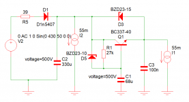
It gets loaded to 485V and the drop is to 480V and you have 5Vpp ripple, so it does never run out of charge, if the current is 200mA it will vary between 485 and 475V, well a little less because of internal resistances of transformer and rectifier.
The 10u cap gets charged through the resistor to the 6.8k to the average of Uin minus 50mA/beta * 6.8k = 0.85V, the output is another 0.75V less. the transistor needs only 0.4V Uce and has 0.9V headroom to vary its resistance to keep the output constant. It will automatically adjust to input variations. The minimum dynamic resistance is about 2 Ohm
The input ripple is kind of sawtooth, the cap gets charged for a short part of the mains cycle, then the load current reduces the charge of the cap until the next cycle.
It gets loaded to 485V and the drop is to 480V and you have 5Vpp ripple, so it does never run out of charge, if the current is 200mA it will vary between 485 and 475V, well a little less because of internal resistances of transformer and rectifier.
The 10u cap gets charged through the resistor to the 6.8k to the average of Uin minus 50mA/beta * 6.8k = 0.85V, the output is another 0.75V less. the transistor needs only 0.4V Uce and has 0.9V headroom to vary its resistance to keep the output constant. It will automatically adjust to input variations. The minimum dynamic resistance is about 2 Ohm
bansuri,
Yes. True. You are right. For this one specific B+ supply.
But we see many newbies who get the idea that the capacitance multiplier is the solution for all B+ supplies.
Not enough capacitance before the cap multiplier, and it runs out of dynamic range (runs out of steam).
I should have stated it that way, it only works with some B+ front ends, and not with others.
Bansuri, Bfpca - this is good information. I have no idea what the fella is using to listen with. I'll take a swag at reducing the 10mV on the driver / screen B+. The output tubes are recent vintage, not the original Amperex Bugle Boy's the amps OEM used.
So the paper tube cap is supposed to be 100uF, but measured low. It also has 120 Ohm in parallel, for the cathode bias of all 4 output tubes... Could that circuit be tricking my handheld capacitor measuring DMM? Probably want that voltage really solid for the best sound -
I would lift one end and test it to be sure. Generally, if I see old caps like that I will replace them if I have something suitable in stock. If it is not bad now, it could go south in the near future and while it’s apart it’s a good time to change it out. Same with power supply caps.
That’s the first time I’ve seen both channels on a PP amp using the same cathode R/C.
It is quite common for manufacturers to use a common self bias R and Bypass C for all 4 output tubes of a stereo push pull amplifier.
Some of those companies select a matched quad of output tubes to ship in the amplifier.
The other companies do not care.
Your mileage may vary.
"You should make things as simple as possible, but no simpler" - Albert Einstein
Some of those companies select a matched quad of output tubes to ship in the amplifier.
The other companies do not care.
Your mileage may vary.
"You should make things as simple as possible, but no simpler" - Albert Einstein
I optimized the circuit for this application
The ripple gets reduced by 54dB
There is no feedback, so it is stable and works under all conditions
The Transistor dissipates 380mW
ciao Bansuri
The ripple gets reduced by 54dB
There is no feedback, so it is stable and works under all conditions
The Transistor dissipates 380mW
ciao Bansuri
Attachments
So after returning the amp, he messages me "It Still Hums..."
I went over to his place with my Fluke meter. We swapped out the 5U4 for a 5Y3 and the hum decreased a bit. with speakers connected, 0.7 mV on one channel, 2.1 one the other - and he hears it. He says "you know I listen to classical and when there's a quiet passage or pause in the music, I can hear it". He says the channel with 0.7 mV is OK.
Swapped output tube pairs - stays with the same channel. Swapped driver tubes - stays with the same channel. 0.2mV residual noise with the amp unplugged.
I'm just waiting to discover the 2mV channel is the one whose output transformer is in-line with the power transformer!
Pretty unsure how to approach a solution, but I took the amp with me and said I'd give it a try. I'm sure it'll be a challenge to reduce the one channel by another mV or so; Rotate the output transformer of the one channel 90 deg? Build up a lifted Ground bus and connect it to the same spot as the quieter channel? Look for any differences between the channels DC operating point?
I'd very much appreciate any suggestion of what I can do. Thanks!
- Status
- This old topic is closed. If you want to reopen this topic, contact a moderator using the "Report Post" button.
- Home
- Amplifiers
- Tubes / Valves
- Reasonable Tube amplifier Hum / Noise