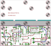
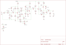
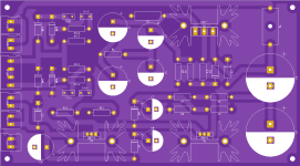
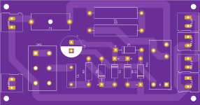
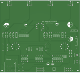
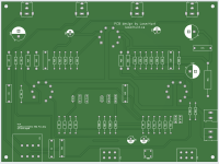
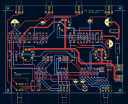
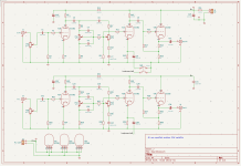
I designed a series regulator for negative voltages (NRS is a Dutch Abreviation for Negative grid voltage)
PCB can be used up to minus -250V at max 50-100mA, consult TIP50 SOA graphs to see how much current is allowable in your use case.
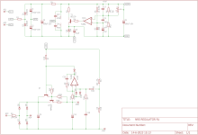
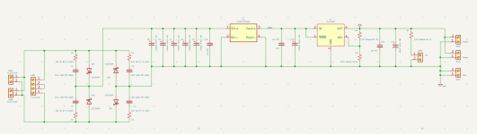
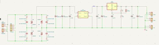
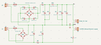
This is a series reg design, It uses the 6.3V normally used for heaters for a voltage doubler that gives 17V no load, this is used for a shunt regulated PSU that gives +10V reference, and -2.4V so TL082 opamps can be used.
R13 and C12 are critical. I need to simulate in spice for the value when i have time.
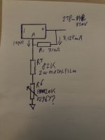
R18 sets the output voltage at 1K per volt. normally I would use a 2W 50PPM metal film type.
The pass stage is TIP50 with a MPSA42 driver.
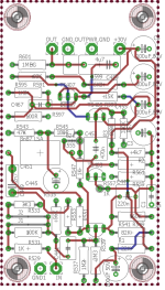
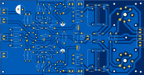
Im trying a new build form factor, I'm using 10x40mm Aluminium bar stock to serve as an interface between PCB and Heatsink.
I have ordered ten boards to play with, can supply assembled and tested modules.
Cheers,
V4LVE.
Post scriptum: Im doing another batch of 6.3V LDO modules: Topic can be found here: https://www.diyaudio.com/community/...d-tube-amp-upgrade.382265/page-2#post-7350338
PCB can be used up to minus -250V at max 50-100mA, consult TIP50 SOA graphs to see how much current is allowable in your use case.
This is a series reg design, It uses the 6.3V normally used for heaters for a voltage doubler that gives 17V no load, this is used for a shunt regulated PSU that gives +10V reference, and -2.4V so TL082 opamps can be used.
R13 and C12 are critical. I need to simulate in spice for the value when i have time.
R18 sets the output voltage at 1K per volt. normally I would use a 2W 50PPM metal film type.
The pass stage is TIP50 with a MPSA42 driver.
Im trying a new build form factor, I'm using 10x40mm Aluminium bar stock to serve as an interface between PCB and Heatsink.
I have ordered ten boards to play with, can supply assembled and tested modules.
Cheers,
V4LVE.
Post scriptum: Im doing another batch of 6.3V LDO modules: Topic can be found here: https://www.diyaudio.com/community/...d-tube-amp-upgrade.382265/page-2#post-7350338
Attachments
Last edited by a moderator:
I'm Selling off some of my parts stock here, parts sold will go directly to keeping the lights on. https://www.diyaudio.com/community/...ts-to-fund-some-projects.400690/#post-7386399
This was a little fun project, its a transistor RIAA, so sorry for posting it in the tube forum. Its the RIAA input section plus VAS from the Philips 22RH590 amplifier.
Attachments
BUG Power PP Amp, my design attached. Included:
A project description with more infos in this board under my name. This was my best of all ever build project. So much fun and satisfaction not to speak about the sound…
Ps.:
Direct wire the 6E5P filament supply with twisted solid wire to the socket. Using the terminal blocks on the board will introduce hum. The GU50 sockets can be mounted on the board if you extend them over the board by about 30mm using posts (holes are on the PCB) and run wires direct down to the board. Don’t put the socket on the PCB directly the GU’s will become quite hot (~260-280 °C). With this, 400mA bias current and XLR balanced input you’ll have a low THD fantastic sounding amp!
- PSU
- GSU
- Simple softstart
- DC filament
- amp, in normal and flipped mirror design
A project description with more infos in this board under my name. This was my best of all ever build project. So much fun and satisfaction not to speak about the sound…
Ps.:
Direct wire the 6E5P filament supply with twisted solid wire to the socket. Using the terminal blocks on the board will introduce hum. The GU50 sockets can be mounted on the board if you extend them over the board by about 30mm using posts (holes are on the PCB) and run wires direct down to the board. Don’t put the socket on the PCB directly the GU’s will become quite hot (~260-280 °C). With this, 400mA bias current and XLR balanced input you’ll have a low THD fantastic sounding amp!
Attachments
Last edited:
BUG Power PP Amp, my design attached. Included:
- PSU
- GSU
- Simple softstart
- DC filament
- amp, in normal and flipped mirror design
A project description with more infos in this board under my name. This was my best of all ever build project. So much fun and satisfaction not to speak about the sound…
Ps.:
Direct wire the 6E5P filament supply with twisted solid ……
I have been looking for good GU-50 designs, and am very interested in your amplifier. Unfortunately the above post is missing some important information. Where is the project description located? No power supply schematic, or more importantly, no HV value on the main schematic. It would be great if you could fill in the gaps.
May I suggest that you move this to your own tread (with administrators help). I think it deserves a thread of its own.
Last edited:
Here’s my re-incarceration of the Lighthouse Electric Sta 1 pre-amp, which has a ton control!
Two versions, mirrored and normal, so, one can decide on which side of the board to stick the tubes.
I also made two versions, one at a bigger size to fit perfectly BRZHIFI BZ2204 series Aluminium case com Aliexpress.
Two versions, mirrored and normal, so, one can decide on which side of the board to stick the tubes.
I also made two versions, one at a bigger size to fit perfectly BRZHIFI BZ2204 series Aluminium case com Aliexpress.
Attachments
Your’re welcome…I have been looking for good GU-50 designs, and am very interested in your amplifier. Unfortunately the above post is missing some important information. Where is the project description located? No power supply schematic, or more importantly, no HV value on the main schematic. It would be great if you could fill in the gaps.
May I suggest that you move this to your own tread (with administrators help). I think it deserves a thread of its own.
Here’s the dedicated thread about this adventure. Should have all you need. Not an easy one, but very rewarding.
https://www.diyaudio.com/community/threads/building-a-pp.382845/
Hello, i like this design and ordered some boards. When i start to populate the boards, have some troubles. I read the post #130 and adjust pot R6 and R5. Set the R1 and then realize that R3 is also not mentioned in schematic. Is that resistor defining the curent, and what Iout can squeeze from boardThis is a board for an extremely compact maida style regulator. In short the EXCmaida R1
") ?
? Today also comes phase inverter boards for ECC82, they look very promising. This is very helpful thread for beginners like me
This schematic values are for 170-200Vac in and 165-205V out if remember correctly.
Yes , that's right .This schematic values are for 170-200Vac in and 165-205V out if remember correctly.
This is handy to knowYes ofcourse.
I got 260-320V with standard components, trimmer is 20K in this example
Hmm i got fake BUZ80 Fireworks happens. will replace with IRF740 or similar for test, also will try LM350 /that i have in stash/. I have one board with 2x PCL86 SE, and need to try to use this circuit to power it. The curent demand is maybe 100mA at 260v for stereo amp. Can i use this board to power the EL84 PP from this tread, ofc 2 boards - one for left and one for right chanell ?
Fireworks happens. will replace with IRF740 or similar for test, also will try LM350 /that i have in stash/. I have one board with 2x PCL86 SE, and need to try to use this circuit to power it. The curent demand is maybe 100mA at 260v for stereo amp. Can i use this board to power the EL84 PP from this tread, ofc 2 boards - one for left and one for right chanell ?I got 260-320V with standard components, trimmer is 20K in this example
If i change BUZ80 for IXYS IXTOP08N100P enhancement mode mosfet, could i change just R2, ( R3 ) , R4 ?
Would use regulator for voltages 285-300 Vdc at 40 mA to 60 mA.
Additionally when using transformer without CT do i connect secondaries just to AC1 & AC2 ?
Thanks, Krca
Attachments
Yes regarding transformer . I'd say no regarding IXTP08N100P ,total dissipation (40W) is too low compared to BUZ80(circuit does not use BUZ80FI) .
NTE2387 could possibly work , but wait for @v4lve lover to reply .
https://www.tme.eu/Document/900698b108d7f3975c943c947132c76c/nte2387.pdf
NTE2387 could possibly work , but wait for @v4lve lover to reply .
https://www.tme.eu/Document/900698b108d7f3975c943c947132c76c/nte2387.pdf
- Home
- Amplifiers
- Tubes / Valves
- V4lve lover's free Gerbers thread