I wouldn't bet on the simulation in this case .That 10 meg bias is using a tube behavior that's not preesent in any tube model.
Grid leak bias, how does it work?
Unless I'm terribly mistaken...
I don't see purely grid leak bias. Perhaps a mix of grid leak bias and degenerated cathode bias (Rk with no Ck).
In the top tube of the cascode input stage, the 2k resistor in the cathode will drop 1V or more, effectively biasing that triode.
The 10M resistor is a simple grid leak. It 'grounds' the top triode grid at the voltage below the 2k cathode load resistor. However, since it is a very large value (10 megohms) it may drop voltage due to a bit of grid current. Perhaps that top 12AY7 is biased so cool it needs a little extra push to draw enough plate current to do its job? If that's the case, then that looks pretty sloppy to me.
But I'm no expert. Just trying to puzzle out why this circuit would be considered anything special.
However, it's a good basis for designing your own circuit in there. A cascode input stage is a nice thing, especially for MM cartridges. The phono stage has a cathode follower output, which is nice. The line stage is a classic common cathode triode DC coupled to cathode follower. Lots of possibilities there (including use of a 6CG7 or 6N6P).
It's funny that there are so many expensive 12AY7 and paralleled resistors in that design. Almost like the main design goal was to spend as much money as possible...
--
Last edited:
i remember reading a lot about this preamp in 2013 when I realized that the schematic was different than the real thing which has two more valves as the upper cascode and the cathode follower have two valves in parallel each of them having that 250k anode resistor and its own 10 meg resistor.Now the thing is that this preamp had fantastic reviews...I wanted to clone it back in 2013 but went for my own design and i don't regret it cause 12ay7 tubes were very expensive and rare at the time for my reach.Now the D3A chosen by me and aquired back then are very rare and expensive too ") Listening to the Kondo M-77 and Gaku Oh | Hifi.com.sg 's Blog
Listening to the Kondo M-77 and Gaku Oh | Hifi.com.sg 's Blog
Listening to the Kondo M-77 and Gaku Oh | Hifi.com.sg 's Blogset of 8 tubes (JJ, some of them selected for low microphonics) came in at €160. Definitely more expensive than some JFETs
(can't wait to finish the building and start measuring....)
thanks for the link, these guys seem to be quite excited with the sound! not sure the clone will keep up with the original though.
(can't wait to finish the building and start measuring....)
thanks for the link, these guys seem to be quite excited with the sound! not sure the clone will keep up with the original though.
Last edited:
so, after finalizing my build and measuring the whole thing, a few interesting points emerged:
- grid leak bias on the first tube - standing current did not change with 10MOhm (original value) or 210k (as per my simulation). Same for the harmonics, H2 at -50dB and H3 at -70dB, identical in both cases. Also, both channels measured identical, seems the guy who did the tube matching did a really good job (not sure if 12AY7 generally matches well, I would suspect it doesnt)
- the simulation had also shown a rise in upper midband with 10MOhm, which had gone at 210k. measurements showed no difference in tonality between the two cases - clearly, the simulation model is out of tune, maybe an extreme case though
- thanks god, at least the RIAA simulation was good - the original values showing another strong upper midband increase, which was measured with a friends' build, and with my values that was gone - flat as a ruler (using an inverse RIAA circuit, of course)
- the output signal had a lot of intermodulation with 50Hz and multiples, pretty much across the entire bandwidth. This preamp will certainly benefit from a cleaner HV supply (regulated), and current sources for the tube heaters for example.
That said, with moderate - loud listening, there wasnt really any audible hum, and noise was low as well. Not the quietest phono I ever heard in my life, but not bad at all....
What really did it for me is the great midrange - lucid, detailed, lots of colours, very nice! Thanks for the tip on the Sprague caps, I have used Jantzen silver foil and that worked out nicely.
i remember reading a lot about this preamp in 2013 when I realized that the schematic was different than the real thing which has two more valves as the upper cascode and the cathode follower have two valves in parallel each of them having that 250k anode resistor and its own 10 meg resistor. ....
Are you saying that the phono stage had two parallel cascodes and two parallel cathode followers? The clone only has double cathode followers on the output....
With a RIAA circuit input impedance of >300K I wonder if that would make a difference
Member
Joined 2009
Paid Member
Saw the same in simulation, you could increase the 33k resistor to 50k, that should help as well.
My build unfortunately isnt ready yet, but will certainly take some measurements when done...
Was there any conclusion what are the right values for proper RIAA in MSL-77 clone? And is the kit ok or any changes to C / R value needed?
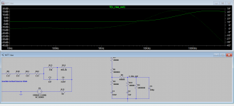
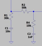
please check this simulation, it shows the new values (the 20800 Ohm resistor is the plate resistance of the previous stage, please ignore).
In essence, good enough to change the 33k to 40k or 50k, and add 10k resistor in series with the 1nF capacitor. This simulation was verified with measurements and corresponds very well.
It gives pretty flat response, and sounds tonally very correct. But taste and opinions vary
In essence, good enough to change the 33k to 40k or 50k, and add 10k resistor in series with the 1nF capacitor. This simulation was verified with measurements and corresponds very well.
It gives pretty flat response, and sounds tonally very correct. But taste and opinions vary
Attachments
Thanks a lot, I will try it. Do you know if the kit uses exactly the same values as original Audio Note schematic? (33k and 1n) Maybe they assembled different values?
How would the RIAA curve look like with original values please? And btw what was the difference while listening both origianl values and tweaked values?
How would the RIAA curve look like with original values please? And btw what was the difference while listening both origianl values and tweaked values?
In fact, I do not know what the original values are, there is quite a bit of conflicting information out there, but it seems that the "clone" values had been taken off the original, so the chances are high that they are the same.
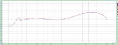
Attached is the measurement result of the original value version. Dont worry about the 50Hz peak, thats due to the setup (hum). You can see strong lift in upper midband. Measurement with my modified values is flat
Soundwise, I found this to be rather significant - very much in your face, getting on my nerves were the impressions I remember. Instruments sounded overly sharp and unrealistic. This was confirmed by a good friend of mine who plays cello and he didnt like it too.
But hey, its just a couple resistors - you could actually put a trimpot and adjust to taste
Attachments
I've started building my M77 clone kit, and have a couple of questions.
Thanks!
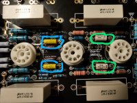
- 1 The kit came with a 1nF capacitor instead of 10nF as is printed on the PCB (see capacitor and position on PCB circled in green). What difference will this make?
- 2 I going to do this modification "change the 33k to 40k or 50k, and add 10k resistor in series with the 1nF capacitor." Just to make sure. The relevant capacitor is the one I have circled in blue?
Thanks!
Attachments
to your question1: most likely it will not make a difference. but if you can get larger caps it would be good, exact value doesnt matter much in my opinion.
question 2: yes that is the right cap. i just desoldered one end and added the 10k resistor with a flying connection.
it pays a lot in sound quality IMHO to replace the 300k/33k/40k or 50k/10k resistors with good quality types (dale rn65 or55, PRP come to mind) and the 1nF/10nF riaa caps with better types as well (silvermica, kemet pps2, .....). if you do, try and get more, to be able to measure and select for identical values for left and right channel, as much as possible. correct absolute value is good, but low deviation L/R is even better
and , while you are at it, replace the coupling caps (the big caps with 0.15/0.22uF) with high quality caps as well. i used jantzen silverfoil, but there is lots of choice and opinions vary
for the output cap it doesnt hurt to put 1uF for good bass.
hope that helps!
I've started building my M77 clone kit, and have a couple of questions.
- 1 The kit came with a 1nF capacitor instead of 10nF as is printed on the PCB (see capacitor and position on PCB circled in green). What difference will this make?
- 2 I going to do this modification "change the 33k to 40k or 50k, and add 10k resistor in series with the 1nF capacitor." Just to make sure. The relevant capacitor is the one I have circled in blue?
Thanks!
Just to clarify - 10nF capacitor assembled in your M77 is the one which shows 1 nF in the schematic? (attached 0.001)
Attachments
to your question1: most likely it will not make a difference. but if you can get larger caps it would be good, exact value doesnt matter much in my opinion.
question 2: yes that is the right cap. i just desoldered one end and added the 10k resistor with a flying connection.
it pays a lot in sound quality IMHO to replace the 300k/33k/40k or 50k/10k resistors with good quality types (dale rn65 or55, PRP come to mind) and the 1nF/10nF riaa caps with better types as well (silvermica, kemet pps2, .....). if you do, try and get more, to be able to measure and select for identical values for left and right channel, as much as possible. correct absolute value is good, but low deviation L/R is even better
and , while you are at it, replace the coupling caps (the big caps with 0.15/0.22uF) with high quality caps as well. i used jantzen silverfoil, but there is lots of choice and opinions vary
for the output cap it doesnt hurt to put 1uF for good bass.
hope that helps!
One thing to clarify - with the modification should I only increase 33k resistor to 50k (R2) or also add a serial resistor R4?
Attachments
More clarification: the original RIAA is not very accurate, and the 2 caps that come with the kit are 10% polyester; they have their place in the trash bin.
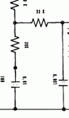
I use 1% polystyrene, NOS from eBay, and LTspice to tweak the values of all 4 resistors: R15, R1, R8 & R13 in the attached schematic. Go slow, small increments, one at a time, or use the .step command if you know your way around LTspice.
I use 1% polystyrene, NOS from eBay, and LTspice to tweak the values of all 4 resistors: R15, R1, R8 & R13 in the attached schematic. Go slow, small increments, one at a time, or use the .step command if you know your way around LTspice.
Attachments
- Home
- Amplifiers
- Tubes / Valves
- Kondo KSL-M77 phono preamp clone project