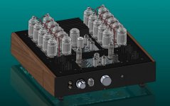
This project has been simmering on the back burner for the better part of two years, but today I finally made some tangible steps towards what will be my most ambitious tube project to date: a 100 watt OTL loosely based on the Alan Kimmel circlotron that appeared in Vacuum Tube Valley: Issue 8.
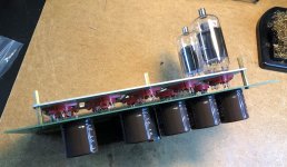
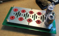
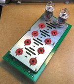
Due to the cost and complexity of the build, I'm trying to approach it with a modular build style. This should allow me to build functional blocks at my convenience without having to commit to buying/building all the parts at once. My first step out of the prototype stage has been the output-section block, which is pictured below. The PCB was designed in Eagle and the aluminum socket plate was ordered from SendCutSend.
The OTL is built around the 21LG6A sweep tube. I found through some research that this tube offered a great balance of maximum current delivery at an affordable price. Far more economical than EL509 or the pricey 6LF6, especially at a quantity of 10 per channel. The driver for the output tube banks is borrowed from Pete Millett's A2 Driver Board and the preamp section is high gain "super triode" configuration leading into a LTP phase splitter.
I have a long road ahead on this project, but for the sake of documentation I will try to update this thread as I make progress. I appreciate any feedback or suggestions as I am very much an amateur and not an EE by trade.
Attachments
-
 OTL_Concept_render.JPG142.7 KB · Views: 1,669
 -
 El509 OTL.PNG295.8 KB · Views: 1,130
 -
 Kimmel_OTL_FPSU.JPG76.7 KB · Views: 919
 -
Audio Circuitry Schematic.pdf211.1 KB · Views: 331
-
 IMG_1795-min.jpg839.4 KB · Views: 494
 -
 IMG_1794-min.jpg878 KB · Views: 1,243
 -
 IMG_1793-min.jpg1,002.8 KB · Views: 1,251
 -
 IMG_1791-min.jpg893.7 KB · Views: 1,335
 -
 OTL_prototype-min.jpg907.1 KB · Views: 1,367
 -
 IMG_1797.jpg758.6 KB · Views: 931
Hi Jerdy.
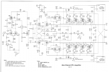
There is an error in your schematic. The capacitor of the fase splitter grid should go to the anode of the penthode driver instead of Vb. Btw, I built something like this some 15 yrs ago with 10 pl519 s each channel. The sound was impressive but so was the heat. Good luck with your project!
There is an error in your schematic. The capacitor of the fase splitter grid should go to the anode of the penthode driver instead of Vb. Btw, I built something like this some 15 yrs ago with 10 pl519 s each channel. The sound was impressive but so was the heat. Good luck with your project!
I checked per your suggestion, but the cap does go to the anode. I just drew the schem a little weirdly LOL.
When you built your OTL did you run in triode mode or in pentode with constant screen voltage? I haven’t seen a lot of comparison between the two topologies. Most people stuck with triode strapped out of simplicity it seems.
When you built your OTL did you run in triode mode or in pentode with constant screen voltage? I haven’t seen a lot of comparison between the two topologies. Most people stuck with triode strapped out of simplicity it seems.
Those OP valves are a bit close together, i think you'll need a fan blowing up from underneath. thermal design often gets neglected in amp design, i think you'll find that chassis will get very hot.
Also be careful of fixing things in stone at this stage, you'll no doubt need to move things round a bit at some stage, layout is optimum with high gain power amps, stability can be lost very easily.
That said nice work so far, well done. Andy.
Also be careful of fixing things in stone at this stage, you'll no doubt need to move things round a bit at some stage, layout is optimum with high gain power amps, stability can be lost very easily.
That said nice work so far, well done. Andy.
Mine is triode connected; Vb is 120v and each tube draws about 150ma. Two triode connected 6bm8 s each drive 5 power tubes. The schematic looks like yours: A srpp ecc83 direct coupled with an ecc82 fase splitter which is capacitor coupled with the cathode followers. Triode connected output tubes have a lower output impedance and that is very important for an otl; you need less feedback to lower Zout. Mine has almost none. Before this one I built an OTL with 6 penthode connected pl519 s which needed a large amount of nfb to make the sound bearable. The result was a flat sounding amp, lifeless, and that was the reason to build the other one.
John Broskie of tube cad journal has written a lot about otl s; highly recommended!
John Broskie of tube cad journal has written a lot about otl s; highly recommended!
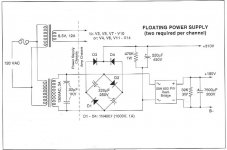
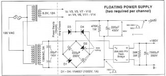
There is something wrong with the power supply.
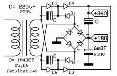
And a possible alternative.
If the capacitors in the doubler age the could get smaller then the output capacitor.Then the get discharged past zero = charged in the wrong way.
C5 and C6 prevent that.
Mona
And a possible alternative.
If the capacitors in the doubler age the could get smaller then the output capacitor.Then the get discharged past zero = charged in the wrong way.
C5 and C6 prevent that.
Mona
Attachments

I built the Alan Kimmel circlotron a few years ago; mine is the "lite" version, with just four EL509 output tubes per channel. It works well, and although not my day-to-day amplifier, which is an OTL using two 6C33C output tubes per channel, I use it occasionally.
One issue I noticed with it is that although one can, of course, adjust the overall DC balance, there tend to be considerable differences between the quiescent current flows in the various tubes in the output stage. (I was finding up to about a factor of two difference between the current flow in one of the paralleled tubes as compared with another.) This doesn't seem to be ideal, but since it would be hard to do much about it without a rather major redesign, I decided not to worry about it.
One issue I noticed with it is that although one can, of course, adjust the overall DC balance, there tend to be considerable differences between the quiescent current flows in the various tubes in the output stage. (I was finding up to about a factor of two difference between the current flow in one of the paralleled tubes as compared with another.) This doesn't seem to be ideal, but since it would be hard to do much about it without a rather major redesign, I decided not to worry about it.
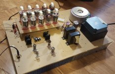
Output tube assembly complete, driver boards complete
It's been a while since my last post, but I would like to share the progress I've made since (and to show this project isn't dead).
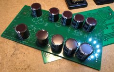
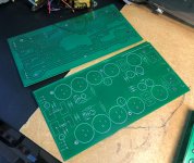
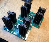
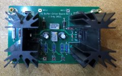
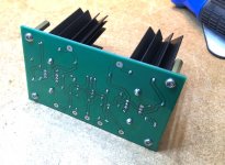
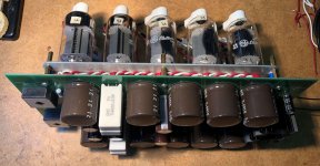
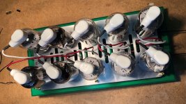
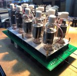
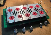
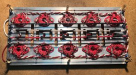
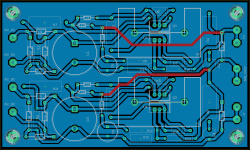
I took suggestions from the previous posts and made the necessary modifications to the output tube PCB. I populated the board with the power supply components and completed the point-to-point wiring under the tube sockets. This is one of the two planned output modules for this amplifier.
I also completed the driver board modules for the left and right output channels. The boards use mosfet followers to provide current drive capability to the control grids of the output tubes. The circuit scheme is the same from Pete Millett's A2 Buffer but with the addition of onboard bias circuitry.
My plan is to continue making one module at a time, chipping away at this until it's done. The effort required in planning this project has slowed me down a bit, but I have confidence I will complete it before the year is out.
Thanks for looking
It's been a while since my last post, but I would like to share the progress I've made since (and to show this project isn't dead).
I took suggestions from the previous posts and made the necessary modifications to the output tube PCB. I populated the board with the power supply components and completed the point-to-point wiring under the tube sockets. This is one of the two planned output modules for this amplifier.
I also completed the driver board modules for the left and right output channels. The boards use mosfet followers to provide current drive capability to the control grids of the output tubes. The circuit scheme is the same from Pete Millett's A2 Buffer but with the addition of onboard bias circuitry.
My plan is to continue making one module at a time, chipping away at this until it's done. The effort required in planning this project has slowed me down a bit, but I have confidence I will complete it before the year is out.
Thanks for looking
Attachments
-
 two_boards.jpg611.4 KB · Views: 232
 -
 topside.jpg276.9 KB · Views: 209
 -
 underside.jpg286.9 KB · Views: 189
 -
 caps_tubes.jpg467.9 KB · Views: 232
 -
 top_view.jpg447.3 KB · Views: 329
 -
 output_assembly.jpg672.2 KB · Views: 327
 -
 boards_assembled.jpg439.9 KB · Views: 270
 -
 underside_wiring.jpg712 KB · Views: 364
Heat will definitely be an issue. My plan is to use two or more 80mm or 120mm high static pressure, low noise fans to create positive pressure within the enclosure. Ideally, the air pushed through the space provided between the tube mounting plates and chassis will be able to provide some cooling.
Power supply for A2 driver and bias network
I made some progress on the bipolar power supply for the A2 driver and bias networks. It's a +/- 150V regulated PSU based off of Pete Millett's Maida-style regulator.
To get the +150V and -150V rails I stacked regulators one on top of the other. It tests well in LTspice, so I feel comfortable ordering the parts. However, I plan on waiting until breadboarding confirms the performance before ordering PCBs.
Attachments
Perhaps worthwhile including a tuned snubber across that secondary winding, given the likely low impedance of the winding and the high peak rectification current and the standard diodes.
Fusing a HT secondary winding is problematic as one side would have screen supply but no anode supply. One practical method could be to use a fuse or cb with a trip contact that then disables the other side's HT, but that kind of solution may be difficult to implement. If you do just use primary side fusing then I'd suggest keep 'as close to the bone' as practical with respect to maximum normal current draw for each separate B+ feed transformer.
You may want to test if the 4R7 cathode resistor can act as a poor mans fuse, or add such a fuse (and an indicator or extended monitor), as a way to prevent collateral damage if one of the output tubes fails (and also to make easier maintenance checks of individual bias currents).
In hindsight, there may be a small benefit in angling each tube base so that the hottest portion of each tube's anode/glass does not point to the same portion of hottest anode/glass on the adjacent tube in the other row.
Last edited:
Perhaps worthwhile including a tuned snubber across that secondary winding, given the likely low impedance of the winding and the high peak rectification current and the standard diodes.
Yes, I am aware of the high peak inrush current from the toroids. It's enough to make the room lights dim for a split second. I will look into this in addition to the resistor/relay circuit I was planning on adding to the primary side.
You may want to test if the 4R7 cathode resistor can act as a poor mans fuse, or add such a fuse (and an indicator or extended monitor), as a way to prevent collateral damage if one of the output tubes fails (and also to make easier maintenance checks of individual bias currents).
Finding out when the resistors fail would be a sensible move. The biggest risk in the failure of a circlotron amp is too much DC current across the speaker coil. At worst this would be the the full quiescent current of five output tubes (250mA to 500mA max). A detection circuit to detect imbalance across the outputs might be an option. As for measuring individual tube bias, I'm not super concerned about that. The resistors will provide some minor correction. I've read that the Atmasphere circlotrons don't bother with tube matching or individual current adjustment since it's diminishing returns for the effort.
In hindsight, there may be a small benefit in angling each tube base so that the hottest portion of each tube's anode/glass does not point to the same portion of hottest anode/glass on the adjacent tube in the other row.
I'm hoping some forced air coming through the chassis from below will compensate for the close spacing. I've done a prototype with this spacing and it was hot but not absurdly so. Much of the heat comes from the class A operation and I tend to run in the low 50-100mA range for longevity.
Thanks for your observations. I need this kind of feedback to slow me down so I don't make any critical mistakes.
The tuned snubber (eg. see the Quasimodo threads) aims to alleviate diode commutation related noise - and is only partly related to primary winding impedance and not related to mains inrush suppression.
The output stage cathode current sense resistors are more about easy confirmation that a particular valve is working, and if it has degraded - that kind of maintenance testing is preferably at least periodic, or linked to some kind of monitor - so not related to a PP balance mindset, but rather a concern about failure or imbalance that causes the other parallel valves to have to over-exert themselves and that stress causing notable reduction in service life, or as you indicate, speaker damage.
The output stage cathode current sense resistors are more about easy confirmation that a particular valve is working, and if it has degraded - that kind of maintenance testing is preferably at least periodic, or linked to some kind of monitor - so not related to a PP balance mindset, but rather a concern about failure or imbalance that causes the other parallel valves to have to over-exert themselves and that stress causing notable reduction in service life, or as you indicate, speaker damage.
Any time you build an amp, tube or solid state, with no output trafo or capacitor, and you’re running a power supply over about 20 or 25 volts you need a DC protect. Trouble is, people don’t like relays in series with their speakers. If you’re ready planning some sort of soft start power management, attack it there. Have the DC condition shut the amplifier down. Open the relay across the soft start resistor and *latch* a 120v-coil relay in series with the resistor open. One little piece of sand sequined - a MOC3010 optoisolator. You want it to occur more quickly? Crowbar the screen supply at the same time. That reduces emissions in the tube quick.
Fusing the HT is pretty simple if you plan ahead a little. Fuse the primaries, not the secondary. Dangerous to fuse that much DC anyway. And fuse the output tube heater supply on the same fuse. If screen voltage is still there, there won’t be any emissions. If one side went down and the other side is still up, you will also trip the DC protect.
When you start playing with big amplifiers, you want to develop and vet all of the supervisor and protection circuits before any sort of high power test. And all of your voltage regulator circuits. You don’t want any mosfets failing short on you, and many types have very poor DC SOA.
And about the Quasimodo snubbers - tube amplifiers always seem t require them, many times even if you use fast rectifiers. Faster rectifiers pushes the ringing frequency up but maybe not high enough for the losses to damp it. Lots of turns makes lots of capacitance and inductance. You may get away without it on your basic transistor amp and the same VA rating trafo at 5X the voltage rings like a bell.
And where did you get those pretty red compactron sockets?.
Tube amps are the least likely to need HT winding snubbing imho, due to relatively high winding resistance and shunt capacitance, and relatively low filter capacitance. The HT on this tube amp is not typical, due to the low 130Vac winding voltage and high winding current and huge proposed filter cap - that makes it more equivalent to an ss amp, and pushes the dI/dt up at the time the diodes are turning off.
Fusing the secondary winding is very practical imho, especially if the transformer has multiple secondary windings. It may also provide better discrimination than a primary side fuse if that fuse was up-sized due to transformer in-rush.
Fusing the secondary winding is very practical imho, especially if the transformer has multiple secondary windings. It may also provide better discrimination than a primary side fuse if that fuse was up-sized due to transformer in-rush.
- Home
- Amplifiers
- Tubes / Valves
- 100 Watt sweep tube Circlotron OTL (WIP)