Those fat tubes are EL509II's? They rather resemble KT88's, I think.
Best regards!
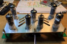
Well spotted - I posted the wrong pic! This one is a second circlotron I build using KT120's. The only significant disadvantage I can see with using an output transformer is that the drive voltage is high to the output stage due to the higher impedances. I use 6SN7 cathode followers with +/- 350V supplies to drive the grids.
The sound is as good as anything I've heard from tubes. Using streaming from Tidal and into Vaff I-66 speakers. Some people are really taken aback when I show them the hook-up wire I use for the (high impedance) speaker cables
not surprising since voice coils are several meters of #28 magnet wire...
Someone told me once the easiest way to turn a sterile solid state amp into tube sound is to put a 1 Ohm resistor in series with the speaker cables!
That will simulate a higher output impedance but the harshness often associated with solid state (caused by a lack of feedback at higher frequencies) will still be there.
Progress Update: PCB assembly and Testing
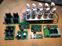
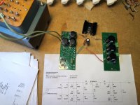
As of this writing, almost all the PCBs required for one channel have been assembled.
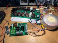
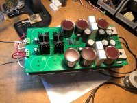
The soft-start/fuse board has been tested with the completed floating output PSU and it successfully limits inrush when faced with the full capacitance on startup (2nd pic).
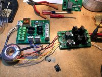
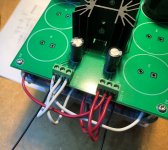
Third pic is the testing of the bipolar PSU comprised of two "stacked" Maida-style regulators (courtesy of Pete Millett). The positive and negative rails come out to +143V and -142V, respectively.
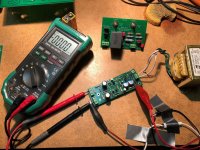
4th pic shows the DC offset detection board under test. A half-dead 9V battery on the input triggers the shutoff as designed. It is powered by 12.6V from the excess heater windings. There is only one board which monitors both output channels. It also provides a turn-on mute and AC-off mute for both.
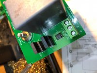
A closeup of the mosfet relay on the speaker output terminals is shown in pic 5. the tiny si7852 mosfet driver is the smallest component I've ever had to solder, but I managed to keep it pretty clean.
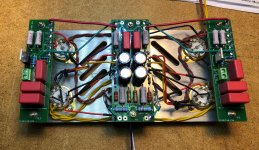
Pics 6 & 7 show rev C of the floating output PSU board in it's near-final assembly state. This was the board I ended up having redone due to significant suggestions made earlier in this thread. I also gained a lot of experience with board layouts since the first revision, so I was able to shrink the size down considerably.
Last two pics show the completed preamp module. It's an odd mix of point-to-point and PCBs. The end result is still a lot cleaner than a completely p-t-p style. I will test it as soon as I finish the HV reg module, which now remains the last module that I need to complete.
As of this writing, almost all the PCBs required for one channel have been assembled.
The soft-start/fuse board has been tested with the completed floating output PSU and it successfully limits inrush when faced with the full capacitance on startup (2nd pic).
Third pic is the testing of the bipolar PSU comprised of two "stacked" Maida-style regulators (courtesy of Pete Millett). The positive and negative rails come out to +143V and -142V, respectively.
4th pic shows the DC offset detection board under test. A half-dead 9V battery on the input triggers the shutoff as designed. It is powered by 12.6V from the excess heater windings. There is only one board which monitors both output channels. It also provides a turn-on mute and AC-off mute for both.
A closeup of the mosfet relay on the speaker output terminals is shown in pic 5. the tiny si7852 mosfet driver is the smallest component I've ever had to solder, but I managed to keep it pretty clean.
Pics 6 & 7 show rev C of the floating output PSU board in it's near-final assembly state. This was the board I ended up having redone due to significant suggestions made earlier in this thread. I also gained a lot of experience with board layouts since the first revision, so I was able to shrink the size down considerably.
Last two pics show the completed preamp module. It's an odd mix of point-to-point and PCBs. The end result is still a lot cleaner than a completely p-t-p style. I will test it as soon as I finish the HV reg module, which now remains the last module that I need to complete.
Attachments
-
 IMG_2489.jpg648.2 KB · Views: 176
 -
 IMG_2474.jpg315.7 KB · Views: 170
 -
 IMG_2477.jpg693 KB · Views: 159
 -
 IMG_2479.jpg643.7 KB · Views: 163
 -
 IMG_2476.jpg275.3 KB · Views: 161
 -
 IMG_2486.jpg452.6 KB · Views: 65
 -
 IMG_2487.jpg910 KB · Views: 73
 -
 IMG_2498.jpg1,021.3 KB · Views: 84
 -
 IMG_2502.jpg406 KB · Views: 85
Trouble with tube-based regulated supply
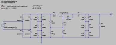
As the title indicates, I have been having trouble getting the 400V regulated supply to behave as expected. In short, there is a disconnect from LTSpice sims to prototype to final. I've been chasing down errors and making adjustments on the bench but I just can't get it match up with the sims.
I have attached the LTSpice files below, but I am prepared to abandon the design in favor of a more compact solid-state solution. The design is old, predicated on work I did (and thought I vetted) years ago when I was far less experienced. It's quite likely I overlooked some serious errors and even the performance I thought I was getting in the prototype was coincidental. At this point I am poised to cut my losses and redesign something safer, simpler, and more efficient.
The problem, near as I can discern, seems to be coming from biasing of the 6AU6. I can't find the adjustment point that draws enough current to lower the 6GY5 control grid to the ~370V required for 400V output while maintaining equilibrium with the other circuit elements. The output voltage is only 10V below the input and excessive screen current is drawn on the pass tube. The VR tube used is 85Vref, which I suspect may be too low relative to the desired output, causing issues with control tubes' voltage, current and biasing. Also possible is I'm using bad tubes and just don't know it. Most of my radio tubes were acquired in unknown condition. However, swapping among multiple 6AU6s changes nothing.
Any input is welcome, especially on suggestions for new HV regulated supply circuit designs.
Attachments
Well, that's the point. How much current does the pass tube allow at a plate voltage of just 10 V? At which screen voltage? You'd feel better with a SS design in this instance.
Best regards!
10va-k is the failure condition. Sims modeled 70-100V across the tube, which should have been within spec. Moot point since it’s not working. Solid state is where I’m heading.
Thanks!
I have attached the LTSpice files below, but I am prepared to abandon the design in favor of a more compact solid-state solution. The design is old, predicated on work I did (and thought I vetted) years ago when I was far less experienced. It's quite likely I overlooked some serious errors and even the performance I thought I was getting in the prototype was coincidental. At this point I am poised to cut my losses and redesign something safer, simpler, and more efficient.
The problem, near as I can discern, seems to be coming from biasing of the 6AU6. I can't find the adjustment point that draws enough current to lower the 6GY5 control grid to the ~370V required for 400V output while maintaining equilibrium with the other circuit elements. The output voltage is only 10V below the input and excessive screen current is drawn on the pass tube. The VR tube used is 85Vref, which I suspect may be too low relative to the desired output, causing issues with control tubes' voltage, current and biasing. Also possible is I'm using bad tubes and just don't know it. Most of my radio tubes were acquired in unknown condition. However, swapping among multiple 6AU6s changes nothing.
Any input is welcome, especially on suggestions for new HV regulated supply circuit designs.
A 6AU6 has a lot of gain and is capable of acting as an opamp entirely on its own. You don't need that extra tube for starters. I don't think you need to abandon the board but some mods could be executed. If this were mine I'd be taking advantage of the gain of the 6AU6 (assuming you don't have cathode/filament arcing issues).
You could run a zener stack in the cathode circuit of the 6AU6 and use a divider network to feed the grid; in this way you could have some feedback gain to more tightly control the output voltage.
From what you describe, I'm picturing something similar to this circuit: (attached).
I can certainly pare my current circuit down by using just the 6AU6 and VR tube. I will mess around with some sims then try it on the bench. Thanks for the helpful suggestions.
Attachments
From what you describe, I'm picturing something similar to this circuit: (attached).
I can certainly pare my current circuit down by using just the 6AU6 and VR tube. I will mess around with some sims then try it on the bench. Thanks for the helpful suggestions.
Although they look nice I wouldn't use a VR tube; IME they make noise and you need low noise on the cathode. I'd use a zener stack bypassed by a capacitance. Don't run them too hot.
Last edited:
I recognize that schematic, Pete Millett’s engineer’s amp. I have borrowed that design before. I have a few more tricks to try on the tube regulator, but I do like the simplicity of the capacitance multiplier.
i used his tricks in many of my tube builds, they work, and if you put 1/2 watt Zeners as gate reference, you have a voltage regulator and a cap multiplier...
i see you also used his A2 mosfet followers, they work good...
I'm ditching the tube-based preamp PSU...
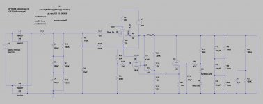
It's been a few weeks since I worked on the PSU issue due to some hectic life circumstances, but I finally got a chance today to completely redo the regulator topology. And it didn't work...
At this point I'm ready to scrap the tube-based design. I'm not sure if my sim models are way off or I'm using bad tubes. Either way, I have no confidence in the design from this point forward so I'm going full solid state. I plan to shamelessly copy Pete Millett's DCPP PSU design. It's simple, I have the parts on-hand, and I know it works well so I will let that be then end of it.
Attached is the LTspice schem capture for reference. I've been waylaid by this particular module for too long and I'm itching to get back on track. I appreciate the suggestions, and I'm just a tad disappointed I couldn't fix the original design.
Attachments
Bench test of the new PSU has been completed. 500V in, 400V out. Very simple with far fewer "moving parts", so to speak.
I will have to do a new board for this module at some point, but as-is I should be able to get on with testing the completed preamp module.
I will have to do a new board for this module at some point, but as-is I should be able to get on with testing the completed preamp module.
Attachments
I'd love to hear it when it's finished! Fuse AC, not DC. Reason is that AC goes through 0 crossings, allowing the plasma in a blowing fuse to extinguish. With DC there's no opportunity for that, and the fuse, especially if it's in an enclosed fuse holder, could cause a fire.
I'd love to hear it when it's finished! Fuse AC, not DC. Reason is that AC goes through 0 crossings, allowing the plasma in a blowing fuse to extinguish. With DC there's no opportunity for that, and the fuse, especially if it's in an enclosed fuse holder, could cause a fire.
Trying to post updates regularly! Yes, I've got all my fuses on the AC side. I have a distribution + Soft Start board that handles all the primary fuses for each major power module. All are fast-blo and sized as close as possible to max nominal current draw. Pic attached shows the fuse board with soft start control on the left.
Attachments

- Home
- Amplifiers
- Tubes / Valves
- 100 Watt sweep tube Circlotron OTL (WIP)