Your build does not look scary to me. I think it is quite neat.
The 1M grid resistor is not in the schematic but I suppose it's there in your amp. Most of the time you see that the gridstopper is in between the gridleak resistor and the g1 connection on the tube socket. But I don't know if an other way to connect them causes your problem.
In my guitar amp builds, I allways connect the 1M gridleak resistor straight on the input plug, while the gridstopper has to be placed as close to the connection of g1 on the tube socket. But I don't have experiences with long shielded cables in between the input and the first tube (I allways place the input and the first tube as close as possible to each other).
Is there a reason for biasing the two 6V6's so low as you did? With the 330 Ohm cathode resistor, you are running the tubes at only 6,3 Watt anode dissipation each, so at about half of their maximum rating.
Last edited:
I only biased it to medium. It has just the right balance of clean and distortion at max volume that I like to have. It's also a head that will sit in my studio turned on for hours so the tubes will last much longer. I just need to get rid of that rumble that I've put in now. I'm kicking my self for not leaving it alone. It only starts at about 7 and it's not super obvious but once I've heard it, I can't un-hear it and it's gonna haunt me when I play. Did you hear it on the sample? Sounds almost like something is loose and rattles.
I just listened to it (should have done that earlier but I have issues between my PC and my outboard soundcard; the level of my PC is way higher than any of the other inputs).
I hear the distortion you mean. I have no way of telling what causes it.
Do you have a scope, or can you borrow one? A scope can tell you wether or not you are dealing with oscillations.
Edit: Are you using the original OPT? And did you here your amp after the change of the cathode resistor to 330 Ohm, but without the problems you now face?
Last edited:
Think you have got fixated with screened wire. I think you have a different issue. If it is micro-phonic I would check you soldering joints. If could even be your wiring of the NFB was wrong before your tidy up.
If you have rumble maybe your close to motor-boating so the instability may be at LF. Moving from fixed bias to cathode follower with caps to ground may affect LF stability. Try a bigger cathode bypass cap.
If you have rumble maybe your close to motor-boating so the instability may be at LF. Moving from fixed bias to cathode follower with caps to ground may affect LF stability. Try a bigger cathode bypass cap.
Last edited:
Yes probably some kind of oscillation but only on the pick of the string, the initial loudest signal. Strange it gets better and worse from time to time. So far I've checked everything including tubes and tried shielding wires but no change. I didn't try to change bias or OPT. Maybe repositioning the OPT will do something, I'll try. And have no scope so it's trial and error type of work.
Similar happened to me years ego. I've build an amp on the bench in two hours, wires all over the place and it worked great. Than I've put it in the chassis and spend a month getting it work right. I think it was ground problems back than.
Similar happened to me years ego. I've build an amp on the bench in two hours, wires all over the place and it worked great. Than I've put it in the chassis and spend a month getting it work right. I think it was ground problems back than.
Right changing a 12AT7 for a 5751 (more like a 12AX7) will increase the gain a lot.
The 12AT7 has a mu of 60, the 5751 has a mu of 70, and the 12AX7 has a mu of 100.
The gain with a 5751 in this circuit will hardly be more than that with an 12AT7.
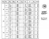
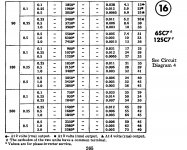
These are the rc-data from the RCA Receiving Tube Manual for the 12AT7 and the 6SC7 (mu = 70 / Ri = 53K / S = 1.325mA/V, so very close to the 5751). The voltage gain for both tubes at about 180 V and with a load resistor of 100K and a cathode resistor of around 1K is the same: 25.
Attachments
I will say it one more time:
There is Tubes / Valves
&
There is Instruments & Amps
If you post a Guitar amp in the Tubes / Valves section . . .
Then in Post #1, Say "This is a Guitar Amp"
Thank you!
(For people like me that see something about striking a string, it does not automatically trigger in my mind that this is a guitar amp).
And, for a Pseudo Current Source (resistor) on a cathode coupled phase splitter, if you change the tube from a 12AT7 to a 5751,
you not only need to change the bias resistor, you need to change both the plate resistors to get the amplitudes balanced.
(or do not pay attention to that, you may like the additional 2nd harmonic distortion you will get when that detail is not properly 'fixed').
Failure to fix the phase splitter, will give you less maximum power, but will get you more 2nd harmonic distortion.
Last edited:
Software and I do not work well together.
I could not get it to calculate the correct values, I had to enter the values,
and then adjust them until the gains matched.
There probably is a way to get it to do it automatically, but I should not have to
learn some clunky software interface.
Great for Computer Geeks!
I would rather use an LM334 or LM317 as a current sink, and then just use
equal plate loads . . . Done!
And guess what, the gains match!
No requirements to keep adjusting.
Well I think I've found the problem. One oxidized connector in 12AX7 tube socket. When I put the tubes back after I fixed the wiring somehow that pin began to be intermittent even though I took the tubes out several times in the process. I measured and cleaned all sockets before I've build the amp but looking at this particular socket hole with magnifying glass, it had quiet a layer of black inside for some reason. Perhaps it was arcing in the first place.
I used E string to file the hole out, now it seems ok (so far!). Spend two day nearly rebuilding the amp because of that, who would have thought.
But I want to say thanks to you all for trying to help, I did learn few things along the way so it wasn't wasted and perhaps someone will have same problem one day and will read this before going crazy.
Last edited:
I recently replaced all 6 input/driver tubes tube sockets (like 60 wires etc) on an old Harman Kardon Citation II amp.
ALL those 9 pin sockets are intermittent/loose and corroded.
If the tube rocks at all in the socket - REPLACE IT.
It's not an option, it's Mandatory for reliable operation.
Take the hint from an old seasoned tech.
ALL those 9 pin sockets are intermittent/loose and corroded.
If the tube rocks at all in the socket - REPLACE IT.
It's not an option, it's Mandatory for reliable operation.
Take the hint from an old seasoned tech.
- Status
- This old topic is closed. If you want to reopen this topic, contact a moderator using the "Report Post" button.
- Home
- Amplifiers
- Tubes / Valves
- Negative feedback shielding