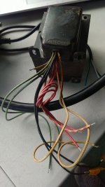
Can someone help me to identify this tube amp power transformer?
There are no markings whatsoever but I have verified that it is good. The lead insulation is braided cloth. I'd like to try and get the ampere ratings for the windings.
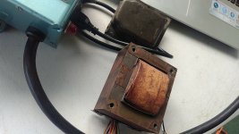
The core size is EI-96 80mm x 96mm (3-1/8" x 3-3/4")
The core thickness is 41mm (1-5/8")
Weight: 5 lbs., 5 oz.
The primary measures 3.5 ohms
The HV secondary measures 168 ohms total
Here is what I measured:
BLK - 120V input
BLK - 120V input
RED - 380V
WHT/RED - CT
RED - 380V
GRN - 3.2V
WHT/GRN - CT
GRN - 3.2V
WHT - 5V
WHT - 5V
Thanks.
There are no markings whatsoever but I have verified that it is good. The lead insulation is braided cloth. I'd like to try and get the ampere ratings for the windings.
The core size is EI-96 80mm x 96mm (3-1/8" x 3-3/4")
The core thickness is 41mm (1-5/8")
Weight: 5 lbs., 5 oz.
The primary measures 3.5 ohms
The HV secondary measures 168 ohms total
Here is what I measured:
BLK - 120V input
BLK - 120V input
RED - 380V
WHT/RED - CT
RED - 380V
GRN - 3.2V
WHT/GRN - CT
GRN - 3.2V
WHT - 5V
WHT - 5V
Thanks.
Attachments
Last edited:
If you have a bunch of wirewound resistors laying around, you can load up each secondary till you see the nominal rated voltage. For example, if you put a 5 ohm resistor on the 6.3V winding and you see it dip from the 6.4V you have now to 6.3V, you can make an estimation about what kind of current you can draw from the winding.
As you load each winding down, the others will drop a little more.
The big question mark would be the 380-0-380, which is probably supposed to be 720V CT loaded?
As always, use resistors that can handle much more dissipation than you put through them running these tests, otherwise you'll just make smoke.
You can actually guesstimate current ratings pretty accurately if you know the nominal voltages and can measure secondaries offload voltages and DCRs (which isn't that easy for heater windings).
Irated = (Voffload - Vnominal) / (2.1 x DCR)
The above formula works for good quality (i.e. correctly calculated and built) transformers, so checking the results by measurements under load wouldn't hurt either.
Irated = (Voffload - Vnominal) / (2.1 x DCR)
The above formula works for good quality (i.e. correctly calculated and built) transformers, so checking the results by measurements under load wouldn't hurt either.
Thanks everyone for the input.
This is what I came up with:
2.5 ohm across the 5V winding - reads 5V with the 2A load
2.0 ohm across the 6.3V winding - reads 6.26V with the 3.13A load
5.238K across the entire secondary - reads 736V with the 140mA load
I couldn't leave it powered on for very long because my 5.238k kluge was barely enough wattage.
The formula posted by TG suggests that the secondary is rated for ~125mA
I was hoping to use this for a mono Class AB amp. 2 x 6L6GC + (3) 300mA heater preamp/splitter tubes + 5AR4 rectifier.
I simulated in PSUD2 and it looks like I would be right at 360V for the power tubes if I use a little series resistance on the transformer secondary.
Looks like this PT might be right on the verge of not being adequate amperage. I guess I could build it anyway and see if it melts. It was free, so I could always replace it.
- Status
- This old topic is closed. If you want to reopen this topic, contact a moderator using the "Report Post" button.
- Home
- Amplifiers
- Tubes / Valves
- unknown power transformer