While in theory you have the schematic captured, but the silver wire transformers, blackgate capacitors, silver switches, silver capacitors, Silver wire, silver jacks, and custom resistors are all part of the overall sound of the original amplifier. You get a taste , but not the full flavour without them.......
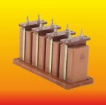
True, the transformers are solid silver primary and secondary. The wire is silver wire reflowed with rhodium/copper. The capacitors are the same as audio note rebrands (Miflex). The resistors are culled from 2000 era land cruiser. The switches are german Mercedes (Dreger) brand switches. The jacks though, I must have missed out choosing zinc copper plated with nickel gold. The electrolytic capacitors are old Siemens automotive grade typically used in Mercedes military G Wagen and Unimog.
The transformer cores come from a 2000 era land cruiser. We may be considering the overall cost of the audio note equipment.
Personally, I don't think the Audio Note equipment comes within a similar league as a amp built with an intention. Not to say this iteration has all the moving parts of a 2000 era land cruiser either.............
Last edited:
While in theory you have the schematic captured, but the silver wire transformers, blackgate capacitors, silver switches, silver capacitors, Silver wire, silver jacks, and custom resistors are all part of the overall sound of the original amplifier. You get a taste , but not the full flavour without them.......
nonono, its the copper chassis that sets the sonic signature.

Actually it s all of those things, circuit design, fabrication detail, and parts metallurgy which make up the sonic signature. The copper chassis being non-ferrous is another - just ask JC . Have fun, me i’ll stick with all discrete, direct coupled, all jfet/fet, balanced, shunt regulator powered designs....
Yeah, but does it sound great when you shift it into 4WD-Low and lock the diffs?
Great for cleaning up those muddy bass notes.
The original Ongaku was a transformer coupled amp designed and built in Japan by Kondo. Few were made and those sold for lots of money in the late 80's. They were highly regarded amps.
In the early 90's Audio Note of the UK used the Ongaku name to sell an amp using a similar, but not identical tube lineup. I don't believe that the true schematic was ever released for the non DIY version. Audio Note (UK) began selling parts and complete kits for a DIY version, but the tube lineup had changed again slightly.
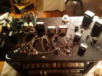
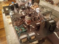
I see nothing in these pictures that resemble any known iterations of an "Ongaku" although there are some parts that might be used in the construction of a 211 based amplifier. Most of the transformers do appear to be Hammonds, yet the words "The transformer cores come from a 2000 era land cruiser" appear in the text, along with references to other car parts.
I built audio amps, and high performance cars in the same time frame, virtually ZERO components interchange......tell me what part of a land cruiser contains transformer cores?
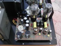
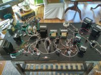
The pictures here appear to be a random collection of stuff, with maybe some heater / filament wiring in place. The board full of opamps with the rats nest of caps soldered on top in parallel with the existing electrolytics certainly doesn't fit. What are you trying to tell us here?
Back in the early 90's a coworker in the plant where I worked bought many of the critical components including the transformers for the DIY Ongaku build from Audio Note UK, but became rather ill before everything arrived. He decided that playing with 1000 volts was not advisable in his current condition so he sold me the parts and bought some fancy mosfet amps.
There were several versions of the Audio Note DIY schematic, some containing errors (backwards electrolytic caps, and illegible numbers). One appeared in Sound Practices Magazine in 1992. I built that amp with the parts I bought. I wound up selling it within a year. I decided to redesign it and make another. I still have that one.
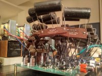
The design iteration looked like this.....
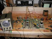
Breadboards with Fahenstock clips were created for each stage. Experiments were done to figure out what worked best. Several different topologies were tried for each stage optimizing each individually before tying them all together. The first picture shows a triode stage loaded by a vacuum tube CCS, IXYS CCS chips did not yet exist.
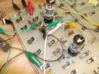
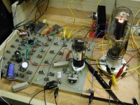
The second picture shows a 45 being tested as a driver to make a large voltage swing without distortion.
The third picture shows the original triode stage is now loaded with a mosfet based CCS, after experimenting with the constant current diodes still seen in the clips on the input stage board. The 45 is now loaded and buffered with mosfets mounted on the heat sink, and driving the 211.
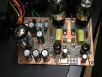
I put all the driver stuff on a PC board and used it in the first iteration of the final "Ongaku 2" or "O2" amp build. Heat build up was a problem so the silicon devices in the middle got heat sinks, and the filament dropping resistors were replaced by a regulator chip. Some will recognize that this is the very first prototype of the Tubelab TSE board.
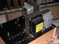
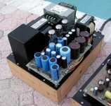
The original power supply had an Audio Note transformer and a Stancor high voltage choke, I sold the AN transformer and the HV choke since the second iteration power supply had a bigger power transformer and a low voltage choke in the ground side of the HV. This supply got me almost 1100 volts, where the original got me about 950 volts.
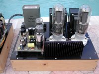
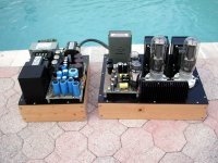
The final amp build got a newer version of what became the TSE board. This is one of two working prototypes that still exist.
The amp was finished in 2005 and still exists today, but doesn't get used. I have curious grandkids and there is exposed high voltage on both chassis of that amp. Maybe someday I will rebuild it.
Attachments
-
 DSCN4255.JPG72.9 KB · Views: 498
 -
 DSCN4260.JPG73.3 KB · Views: 474
 -
 DSCN4873_x.jpg720.5 KB · Views: 423
 -
 DSCN5011a.jpg84.6 KB · Views: 444
 -
 DSCN4387.JPG894.8 KB · Views: 446
 -
 DSCN6830_x.jpg884.6 KB · Views: 305
 -
 Amp_a.jpg302.5 KB · Views: 426
 -
 PowerSupply_a.jpg279.5 KB · Views: 291
 -
 BothChassis_a.jpg338.5 KB · Views: 302
I have the perfect solution to this, I know what I built but am having trouble expressing it here. How about you guys keep this thread for yourself and I'll just take a hike.
I did pay roughly $500 for the schematic by the way from audio note. Perhaps I paid you for the schematics you sent, maybe you remember...
BTW: nice amp tubelab. Very neat.
I did pay roughly $500 for the schematic by the way from audio note. Perhaps I paid you for the schematics you sent, maybe you remember...
BTW: nice amp tubelab. Very neat.
Last edited:
Hey brightcity, don't take it to heart, eveyone is a critic. This certainly looks interesting, I am curious to see how this pans out in the later iterations. One thing that I do wonder about is this, as you have soldered this over a large area, which is obviously not something that can be done with a commercial product due to size restraints, what will be the effect on sound?
Also, there are several car references that I do not understand, can you clarify?
Also, there are several car references that I do not understand, can you clarify?

Sorry, not possible. Every square inch of the board is filled, there will be necessary other parts on another board.
I did come here to hear your opinions, not to post my own. Perhaps we can split the difference (see above post)
I did come here to hear your opinions, not to post my own. Perhaps we can split the difference (see above post)
Attachments
Last edited:
I did pay roughly $500 for the schematic by the way from audio note.
Seriously?

- Home
- Amplifiers
- Tubes / Valves
- Ongaku Build