The two systems in the PCF86 share one cathode, so it can't be used in Dynaco-like topologies.
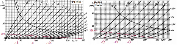
The PCF86 was developed as a mixer (pentode) and oscillator (triode). For mixing duty, it is essential that the mixer is non-linear (more so than a pentode designed for audio, like the EF86). Looking at the curves of the pentode section, I would not use it as a voltage amplifier for audio.
The PCF86 was developed as a mixer (pentode) and oscillator (triode). For mixing duty, it is essential that the mixer is non-linear (more so than a pentode designed for audio, like the EF86). Looking at the curves of the pentode section, I would not use it as a voltage amplifier for audio.
Last edited:
ECF80 makes an excellent audio tube. I have one setup as a Super Linear Cathode follower with two making up each channel. The Triode and pentode can pass just about the same current so this makes them excellent for stacked topology.
The way mine work are :
Triode of first tube as first stage voltage amplifier
Pentode of first tube as bottom of totem pole CCS, second valve with triode as cathode follower loaded on the CCS and finally the pentode triode strapped as the voltage follower on top.
Literally the best thing I ever built and copes with ridiculously high voltages.
Shoog
with ridiculously high voltages.
 not more than 90v on triode in this case ... because of max insulation on heating line
 ")
Avivz , look at the MR71 (? or 78) AF output stage
McINTOSH MR71 vintage tuner upgrade | D a r k L a n t e r n
Last edited:
Some schematics with the ECF80:
Attachments
-
2 x ECC83 + ECF80 + 2 x PL500 pp (Braun CSV60).pdf693.5 KB · Views: 285
-
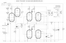 ECC82 dc-coupled c-follower parafeed transformer-coupled + 2 x ECF80 pp (The Dunnit).jpg188.2 KB · Views: 980
 -
Transformer-coupled ECF80 dc-coupled + 2 x EL5000 ul pp (Klein & Hummel V-30).pdf1.5 MB · Views: 220
-
ECF80 dc-coupled + 2 x EL84 ul pp (KEL84).pdf123 KB · Views: 232
-
ECF80 dc-coupled + 2 x EL84 triode pp + 5V4 (RB 1967).pdf201.6 KB · Views: 174
-
ECF80 + 2 x EL84 ul se + EZ81 (Heathkit MA5).pdf435.2 KB · Views: 223
-
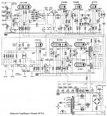
 5 x ECC83 + ECF80 dc-coupled + 2 x EL34 pp + GZ34 (Schaller V35).jpg144.4 KB · Views: 672
 -
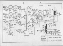
 2 x ECC808 + ECC83 c-follower + ECF80 + 2 x EL500 ul pp (Telewatt VS71H).jpg125.5 KB · Views: 654
Either the PCF 80 and the PCF 86 were designed primarily as frequency changers in TV VHF frontends. By comparing at the pentodes' plate curves, I don't see any sign why the '86 pentode should be more nonlinear than the '80. The main drawback of the PCF 86 indeed is it's common cathode connection.The two systems in the PCF86 share one cathode, so it can't be used in Dynaco-like topologies.
The PCF86 was developed as a mixer (pentode) and oscillator (triode). For mixing duty, it is essential that the mixer is non-linear (more so than a pentode designed for audio, like the EF86). Looking at the curves of the pentode section, I would not use it as a voltage amplifier for audio.
Best regards!
OK, maybe I'm wrong. I thought that even with Vg2max (150 V) it will be hard to find a good loadline/operating point for the pentode section of the PCF86, knowing that you have to stay away from values for Vg1 that might cause gridcurrent. It looks to me that with the pentode section of the PCF80 this is less of a problem, but again, maybe I'm wrong.
Can you suggest a good working point and load for the pentode section of the PCF86?
Can you suggest a good working point and load for the pentode section of the PCF86?
I haven't worked with this tube yet - due to it's common cathode interface . What's your goal? Maximum voltage gain? Maximum plate signal swing? The optimal operating point depends on these considerations.
Anyway, by it's rather high transconduction the pentode supposedly is of frame grid construction, hence not easily to tame indeed, as you can't apply local degeneration easily.
Best regards!
. What's your goal? Maximum voltage gain? Maximum plate signal swing? The optimal operating point depends on these considerations. Anyway, by it's rather high transconduction the pentode supposedly is of frame grid construction, hence not easily to tame indeed, as you can't apply local degeneration easily.
Best regards!
Here is where my knowledge of the workings of tubes probably lacks. But I am eager to learn.
Is there no inherent feedback in this LTP? The triode section has an amplification factor of 17. In the schematic it amplifies with a factor of 10. Than there is hardly any room for that inherent feedback, or is there?
With the voltage between grid and cathode of the triode section being 2.2 V and the input signal being 10Vpp, how come the triode section does not run into grid current (at the positive going parts of the input signal)? Is it because the inherent feedback in the LTP?
More or less the same question for the pentode section: How come it can see 10Vpp (via the cathode coupling) at 1.4 V between control grid and cathode without running into grid current?
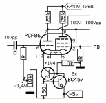
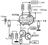
Trying to analyze Mona's schematics: It's a LTP PI with a ring of two type CCS in the common cathode tail. Defined by the 50 ohms resistor and the right BC547's (457 supposedly is a typo) Vbe, the tail current is ~12 mA. In a LTP the common cathodes show half the input AC signal level, so 5 Vpp. As the CCS doesn't refer to GND, but to -5 Vdc instead, there ain't no issue, as the CCS theoretically allows a swing of 6.4 Vss. If I get it right, both plates are at 100 Vdc level and will swing an output signal of 100 Vpp.
Maybe Mona will chime in again and clarify?
Personally, I would have put the pentode at the input.
Best regards!
Maybe Mona will chime in again and clarify?
Personally, I would have put the pentode at the input.
Best regards!
Yes, the 457 is a typo, but that isn't the only error 
The curves for the pentode as triode and the triode have a different scale.
On with 1mA step, the other 2mA and I mixed it up, so the values in the schematic are wrong.
Made a new one.
To see how it works skip the FB = keep the right grid at 0V.
For the voltages, look at the curves.
To get the anode triode from 100V to 50V the grid has to go from -6V to -1,8V and take more current from the source.That means less current for the pentode(triode).To make it possible the grid must become more negative = cathode more positive, from 1,3V to 2,2V.The extra positive has to come from the input,pulling the cathode up.Input needed 6-1,8=4,2V + 2,2-1,3=0,9V, total 5,1V to get 50V out. Is a gain of 50/5,1 = 9,8x.
Mona
Attachments
- Status
- This old topic is closed. If you want to reopen this topic, contact a moderator using the "Report Post" button.
- Home
- Amplifiers
- Tubes / Valves
- Are PCF80 and PCF86 any good for tube amps?