...and in addition to being ultra-low distortion, it is low cost as well. The idea was to use high-impedance DHTs that you can pick up for significantly less $ than the good low-impedance triodes, and a cheap input tube. I also used an inexpensive Edcor 5k:8 25W SE transformer. Nothing exotic.
I ran 520V for B+ and 100mA quiescent current, which gave about 19W output at onset of clipping (still 0.3% distortion, but rising very steeply after 19W).
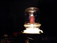
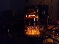
My output tube is an 826, a 60W high impedance transmitting triode, but this approach works well with pentode output stages as well. I actually started this design with 811A in mind. Whatever it was it needed a thoriated tungsten filament, that's for sure. If I had it to do over again, I wouldn't use the 826. Too many NOS tubes are gassy, and without getter material on the inside of the glass you have no visual clues that you are buying a bottle of air. I had a very high rate of returns when purchasing my small stock.
Why call it Corona? Well, the output tube plate, when viewed from above reminds me of the sun's corona. That and the virus by the same name gave me a lot of extra time to work on this.
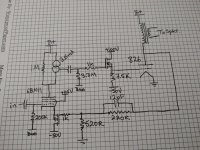
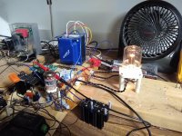
I'll follow up with posts on theory of operation and detailed performance tests, but here's the simplified schematic and a photo of the amplifier itself to start.
I ran 520V for B+ and 100mA quiescent current, which gave about 19W output at onset of clipping (still 0.3% distortion, but rising very steeply after 19W).
My output tube is an 826, a 60W high impedance transmitting triode, but this approach works well with pentode output stages as well. I actually started this design with 811A in mind. Whatever it was it needed a thoriated tungsten filament, that's for sure. If I had it to do over again, I wouldn't use the 826. Too many NOS tubes are gassy, and without getter material on the inside of the glass you have no visual clues that you are buying a bottle of air. I had a very high rate of returns when purchasing my small stock.
Why call it Corona? Well, the output tube plate, when viewed from above reminds me of the sun's corona. That and the virus by the same name gave me a lot of extra time to work on this.
I'll follow up with posts on theory of operation and detailed performance tests, but here's the simplified schematic and a photo of the amplifier itself to start.
It would be interesting to know about the issues you faced that produced the arrangement at the pentode's cathode.
I started out with having the pentode input stage cathode tied to the top of the 520R resistor. It performed pretty well. I was getting ~.14% distortion at 1W. But thinking about it I saw a couple of problems with this approach.
1) Current feedback in the input stage was holding the input stage's gain back. I got gain of about 720 in that arrangement. After buffering the feedback divider with the p-channel fet follower, gain increased to about 2600.
2) Screen current was in phase with the plate current, so makes it even worse, and it isn't even as directly related to the plate current, so it is just causes problems.
Buffering the feedback network from these undesirable AC currents that cause feedback errors drastically improved the effectiveness of the feedback.
The p-channel fet follower is the secret sauce here. Otherwise, it is very similar to what has been done for many decades in a lot of amps. The follower just kind of supercharges the feedback.
I left the output transformer out of the loop to allow the use of cheap iron.
At one point, I considered a differential input stage to fix the same problem but I like this a lot better for the simplicity. Basically I'm just creating a differential amplifier out of a single pentode with two high impedance inputs.
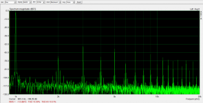
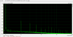
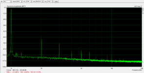
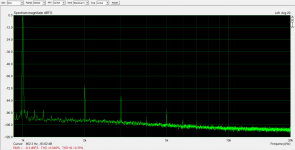
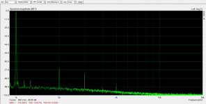
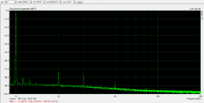
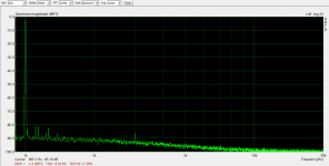
I've attached distortion measurements at various power levels.
100mW: 0.014%
500mW: 0.017%
1W: 0.027%
2W: 0.040%
5W: 0.063%
10W: 0.063%
19W: 0.30%
What's interesting is that cranking level up from 5-10W shows some small shifting around of harmonics but the dominant 2nd and 3rd just stay at the same relative level to the fundamental. I've never seen distortion stay the same proportion with level increase over a range that broad.
Distortion rises very rapidly after 19W. I was watching the waveform on the pentode plate and became afraid to increase level further. The waveform has spikes that made me fear for the survival of the control grid if I tried to maintain that with a continuous high-powered sine wave.
I did destroy the grids on a quad of KT88s in a similar manner once so now I am more careful testing to clipping. I'm comfortable stopping there and calling this a 19W amp.
Attachments
Member
Joined 2009
Paid Member
You have built a front end which I would call a hybrid Rush Cascode. No wonder the gain has increased. There’s some chit chat about it here: The Inverted Cascode
That 826 sure looks great!
That 826 sure looks great!
I bet you could get 28W from that 826 if you tweaked things just a little more")
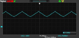
I'm running it at 52W, so there is still 8W available to get that plate to glow a bit redder. Really the operating point that I'm at gives a theoretical ~23W with a lossless transformer. The transformer is stealing some of my power.
The biggest practical limit I have here is that I need a new power transformer to go higher on B+.
Here is the waveform on the pentode plate. Any further increases cause sharp spikes to start forming on both the positive and negative peaks of this triangle wave. Clipping seems to be pretty symmetrical, so I need a higher B+ to get more power.
Unfortunately, I didn't get a screenshot of the spikes.
Attachments
You have built a front end which I would call a hybrid Rush Cascode. No wonder the gain has increased. There’s some chit chat about it here: The Inverted Cascode
That 826 sure looks great!
I'll have to look into the history of the Rush circuit. Thanks for pointing that out.
When I started out using the 6BN11, I made an estimate of what gain could be with a totally horizontal load line (perfect CCS). It was hard to estimate due to the resolution of the curves on the datasheet, but I came up with something around 5000.
I've got a couple of sources of gain reduction. One is the parallel 1M resistor to the CCS and imperfections in the CCS itself. Another is the screen-cathode voltage variations with the cathode swinging around. This gives a very small amount of negative feedback to the screen. I'm not sure how significant 1V of variation is on a screen that sits at 115V, but it has an effect.
The P-channel fet's transconductance is much higher than the tube, so the tube's cathode won't be able to push the fet's source around much. That source is going to pretty faithfully follow the voltage at the feedback divider on the gate. I had considered using an opamp follower to test this idea initially but wiring up a mosfet was easier. Fewer pins, and it worked great.
The 826 really does look good. It's hard to get good pictures with my phone. The 6BN11 looks good too. They were both good tubes for the job, but good looks was also a requirement.
Attachments
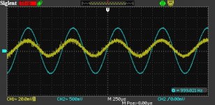
For Zout I got ~0.7 Ohms. Most of that (0.55 Ohms) is copper losses in the output transformer. Since my feedback loop doesn't contain the output transformer, it is beneficial to choose a transformer without high copper losses. The Edcor is pretty good, but there are better ones out there.
To test, I injected a 1Vpk signal into the output of the amp through 50 Ohms and measure the peak voltage at amplifier output with 8 Ohm load connected.
This was up a little bit from my earlier experiments with a 6384 output tube. I expected that, since the 826 has about 2/3 the transconductance of the 6384.
Attachments
I want to make a similar test assembly.
What FETs are you using for the source follower and the feedback?
Steve
The 826 grid driver is a C2M1000170D. You could probably find another fet with higher transconductance that is a lot cheaper. I just wanted to try this one out and see if it was hard to tame. It was not. The p-channel fet is FQP3P50. You could probably also use a lower voltage part with higher transconductance there as well, but I buy FQP3P50s by the bag so I just used one of those.
The CCS is a cascode of DN2540 (bottom) and 10M90S (top).
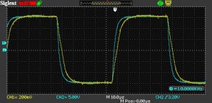
Here's the last measurement I've got. 10kHz Square wave on primary and secondary of the output transformer.
I'll buy some more small-value HV caps next Mouser order I make. All I had on had was 12pF, so that is what I'm using in parallel with the 220k feedback resistor right now. It looks like I could use less and get faster edges but I don't have the parts on hand to play around with that yet.
I'll buy some more small-value HV caps next Mouser order I make. All I had on had was 12pF, so that is what I'm using in parallel with the 220k feedback resistor right now. It looks like I could use less and get faster edges but I don't have the parts on hand to play around with that yet.
Attachments
Interesting!
So, question:
Why not kill two birds with one stone?
Connect 2 (or more) 12pF in series for less C. Then they may not even need to be high voltage rated.
I've got a few 2pF caps as well, so I should be able to come up with some series/parallel combination to back off the capacitance a bit and see what happens.
I added two posts to my blog.
The first is a detailed write-up of this amp: Tube Amps with a Twist: An Ultra-Low Distortion 826 SE Amp
The second is a writeup of the evolution of the experiments that let to this approach: Tube Amps with a Twist: My 6384 SE Experiments
I figured I'd link to them here for anyone interested reading those stories in a more cohesive narrative than discussion threads.
Hi
Excellent write up and experiments. Hats off!
Have you considered connecting the 1Meg resistor from plate to ground instead to improve the PSRR of the driver?
Also, for stability purposes given the drift you mention, why not deriving the screen voltage from the driver output via a resistor divider and a cap to filter AC out and a MOSFET driving the screen? This should help out I think....
Cheers
Ale
- Home
- Amplifiers
- Tubes / Valves
- Corona: An Ultra-Low Distortion A2 DHT SE Amp Prototype