Great information Reinout, beautiful collection, and amazing listening room! Most impressive, I am jealous of your box of HK54  took quite an effort for me to track down 8.
I am planning an A2 design around it. I had thought that if my HK54 supply were to run dry, the amplifier could be rather easily adapted for 35T if need be, it seems that would be accurate based on your impressions, maybe I should plan ahead and collect some as well.
I have one pair of early HK54, 'open plate', however one is slightly gassy, perhaps it can be revived. The other is fully functional, I have found the curves are a bit different than the other 'closed plate' HK54, with more bunching with further excursions into A2, I do wonder if the top was added to accommodate this and improve A2 linearity, 'open plate' curves below.

'Closed plate' curves can be seen here, in post #233: Corona: An Ultra-Low Distortion A2 DHT SE Amp Prototype
If you have any insight into designing for these tubes, I would be happy to hear it the obvious issue is that of plate resistance, I will likely employ some of the feedback methods outlined by SpreadSpectrum in this thread with high-gain pentode input.
took quite an effort for me to track down 8.I am planning an A2 design around it. I had thought that if my HK54 supply were to run dry, the amplifier could be rather easily adapted for 35T if need be, it seems that would be accurate based on your impressions, maybe I should plan ahead and collect some as well.
I have one pair of early HK54, 'open plate', however one is slightly gassy, perhaps it can be revived. The other is fully functional, I have found the curves are a bit different than the other 'closed plate' HK54, with more bunching with further excursions into A2, I do wonder if the top was added to accommodate this and improve A2 linearity, 'open plate' curves below.
'Closed plate' curves can be seen here, in post #233: Corona: An Ultra-Low Distortion A2 DHT SE Amp Prototype
If you have any insight into designing for these tubes, I would be happy to hear it
the obvious issue is that of plate resistance, I will likely employ some of the feedback methods outlined by SpreadSpectrum in this thread with high-gain pentode input.
Last edited:
Good evening LOrdGwyn,
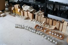
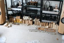
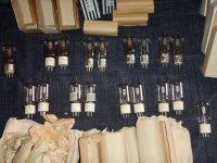
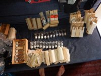
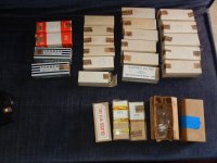
rest assured, before i post my amplifiers/projects here i'm sure to have a lifetime supply of needed goodies.
Included some pics of part of my 35TG and 35T stash....
The difference between early 35's (both T and TG and HK54 as well) and later 35's (T, G and HK54 as well) is the fact that their anode construction is changed.
Eimac closed their anode top completely. This brought the mu from 30 to 39 (hurray for the squirrel cage construction !) but the heat remained stuck inside the structure. If overdriven this caused problems.
H&K came up with a much neater solution with a partially enclosed anode-top. The heat could escape (preventing the anode-soldering to de-solder) but get some extra gain.
It was not done for specific (A2) drive but for pure gain.
Included the datasheets of an early 35T and a later one with higher gain.
Regards,
Reinout
(all GREAT sounding tubes !)
Attachments
I finished the second channel of this 801A A2 amplifier. One slight change was made - I found the Tent Labs heater regulator was injecting a significant amount of noise onto the EF37A grid. Fortunately, I had a filament / heater regulator from Pete Millett on hand, now all is quiet, and it is reflected in the noise floor of the measurements.
Somewhere along the way, the measurements significantly improved in other ways too, I suspect due to a tube swap + the heater regulator swapout.
Output Z: 1.53 ohms (0.8ohms copper losses, approximately)
Power output: 6.2W into 8ohms
1W into 8ohm FFT

HF extension is improved.

1kHz square at 1W - same resonance seen on all squares

10kHz square at 1W

100Hz square at 1W

Having a listen now with headphones out of the jack of the protoboard, parallel 8ohm resistive load, I've found the sound translates quite well to speakers this way. There is always a honeymoon phase, but the sound is very good

Somewhere along the way, the measurements significantly improved in other ways too, I suspect due to a tube swap + the heater regulator swapout.
Output Z: 1.53 ohms (0.8ohms copper losses, approximately)
Power output: 6.2W into 8ohms
1W into 8ohm FFT
HF extension is improved.
1kHz square at 1W - same resonance seen on all squares
10kHz square at 1W
100Hz square at 1W
Having a listen now with headphones out of the jack of the protoboard, parallel 8ohm resistive load, I've found the sound translates quite well to speakers this way. There is always a honeymoon phase, but the sound is very good
Sorry I am hijacking the thread, just one final comment - I lugged this monster up into my stereo with my Snell Js. The sound is nothing short of excellent, very impressive, giving my 6A5G SET a run for its money.
Thanks for your help along the way, SpreadSpectrum. More tinkering to be done in terms of the degree of feedback, but this is not far off from going in a box.

Thanks for your help along the way, SpreadSpectrum. More tinkering to be done in terms of the degree of feedback, but this is not far off from going in a box.
Looks really good. No worries on posting in this thread. I enjoy the discussion.
Some day I'll get around to subbing in a 100TH. Right now I've been messing with the first stage bias servo. The issue I'm having is that there is still a bit of LF overshoot. I want to slow the servo down but it already takes 1:30 to bias up at turn-on. I want to slow it by a factor of 10 but then it will take 15 minutes for the amp to play music, which is unacceptable. So I'm adding a circuit to speed up the servo at power-up. I'd like the amp to be able to play music at ~45 seconds from power-on. The 6BN11 cathodes take ~30 seconds to heat enough for emission.
I've just been really slow at putting it all together.
I finally sorted out the input tube bias servo out so it adjusts quickly at power-up for the first 15 seconds (before the tube is warm) and then slows substantially. This servo was more challenging than any of the power tube servos I have done since the stage had so much more gain, so more opportunity for some small amount of gain to overlap between the audio circuit and the servo with substantial phase shift at some subsonic frequency. I never had oscillations but a little overshoot in the response.
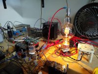
After sorting that out overshoot is gone, and I subbed in the 100TH. It is still at the 53W operating point that the 826 was at, so it is running very cool. It sounds pretty much the same as the 826. I can't tell a difference. But it definitely looks cooler.
Next step will be to design the 750V supply to get a real 100TH operating point.
Attachments
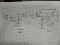
I finished designing and building the ripple rejection circuit. I decided to try something dead simple and see if it was good enough. It seems to be, but I'm always up for any suggestions that won't compromise reliability at these high voltages.
I wanted to get away from a true regulator as dissipation in the pass device can vary wildly. With this circuit, if line voltage goes up a few percent, so will pass device dissipation. With a regulator, you always have to plan for that worst case input voltage sag and then you end up with something that dissipates much more power with high line voltage.
I plan on having a bias servo control bias for the output tube in the end, and I will implement a feature that will try to keep output tube idle dissipation fairly constant with line voltage variations.
I compared this ripple reject circuit with Tom Christiansen's 21st century Maida and this circuit definitely has more output noise and higher Zout. I also compared the amplifier output noise with both regulators and measured no difference, so while the Maida has less noise, the ripple reject circuit's noise floor seems adequate. 120Hz ripple is buried in the noise but if I use the filter feature on my scope, I can just make it out riding on much larger subsonic noise. I'll post some of those measurements when I get time.
Right now I have the 100TH running at 700V, 120mA for a total of about 84W idle dissipation. I'll have to buy another power transformer to get to the 750V target. For now I series connected a 400V and a 120V transformer for this test.
The amp sounds real good and punchy at loud volumes. It is connected to some 70s Sansui speakers that I have in the garage that are quite efficient, so it will make my ears bleed if I turn it up all the way. I haven't taken any distortion measurements yet but those will come.
Attachments
Here is a comparison of Tom Christiansen's regulator output noise to the simple source follower.
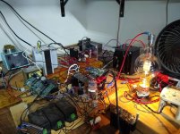
Just as a note, I don't think this messy wiring that I have done in these experiments will do Tom's regulator justice. I've got some ground loop issues here that are sending junk from the switching supplies all around this setup. I'm just trying to show how much worse noise performance got with the simple ripple reject circuit.
Just as a note, I don't think this messy wiring that I have done in these experiments will do Tom's regulator justice. I've got some ground loop issues here that are sending junk from the switching supplies all around this setup. I'm just trying to show how much worse noise performance got with the simple ripple reject circuit.
Attachments
Here are a couple more measurements.
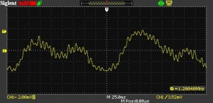
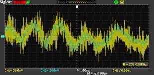
The first is a look at 120Hz ripple. I set the scope input filter to its lowest setting, which I think was like 1.25kHz. Voila, the ripple is visible but very low magnitude, riding on some much larger subsonic noise. The fet follower actually does a pretty good job of rejecting the 120Hz ripple. Higher frequency noise is more of a problem.
The second is monitoring the output of the regulator with music playing. Blue trace is the output at the speaker terminal. Yellow trace is the output of the regulator (AC coupled).
Attachments
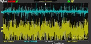
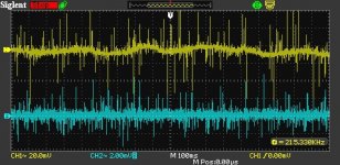
I made a couple of changes to the power supply that seem to have cleaned things up a bit.
First, I added a ferrite bead and .1uF cap to bypass the filtered gate voltage. This seems to have really quieted things down. I also cleaned up the ground wiring of this prototype system. It is still a bit of a mess and I don't think I'm up for really sorting it out until I build the real amp in a chassis.
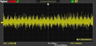
Attached are some pictures. Yellow trace is the power supply output noise. It is mostly high frequency stuff. If I filter it to 20kHz it almost disappears.
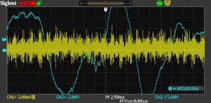
The second picture is the amp playing music. Blue trace is the speaker terminal. As you can see, the mosfet source is holding things pretty steady. I think my previous traces must have had something going on with the grounding because things look much better now.
I was a bit worried about running a mosfet in linear duty at voltages and currents like this. The $15 mosfet that I originally chose for this position has been backordered for almost a year so I bit the bullet and bought a $40 part that should be more than happy in this duty.
Overall, I'm very pleased with the result and have placed an order for a Hammond transformer that should get me another 50V to get a little more out of all of these 100T variants that I have procured.
Once I get the power supply nailed down, I'll do a series of distortion measurements with different output tubes. I plan on getting my hands on a 211 to measure as well, since the datasheet curves make it look like it is the most linear tube ever made. We'll see.
First, I added a ferrite bead and .1uF cap to bypass the filtered gate voltage. This seems to have really quieted things down. I also cleaned up the ground wiring of this prototype system. It is still a bit of a mess and I don't think I'm up for really sorting it out until I build the real amp in a chassis.
Attached are some pictures. Yellow trace is the power supply output noise. It is mostly high frequency stuff. If I filter it to 20kHz it almost disappears.
The second picture is the amp playing music. Blue trace is the speaker terminal. As you can see, the mosfet source is holding things pretty steady. I think my previous traces must have had something going on with the grounding because things look much better now.
I was a bit worried about running a mosfet in linear duty at voltages and currents like this. The $15 mosfet that I originally chose for this position has been backordered for almost a year so I bit the bullet and bought a $40 part that should be more than happy in this duty.
Overall, I'm very pleased with the result and have placed an order for a Hammond transformer that should get me another 50V to get a little more out of all of these 100T variants that I have procured.
Once I get the power supply nailed down, I'll do a series of distortion measurements with different output tubes. I plan on getting my hands on a 211 to measure as well, since the datasheet curves make it look like it is the most linear tube ever made. We'll see.
Attachments
The giant IXYS IXTK8N150L mentioned on his power supply schematic can eat half an amp with 1 KV across it (500 watts of dissipation).
This is the biggest SPECIFIED SOA of any mosfet that I have seen, and yes it costs $40, so I am busy blowing up cheaper fets in my amp design.
The $9 IXTP15N50L2 is big enough for my application and I have not blown one yet.
This is the biggest SPECIFIED SOA of any mosfet that I have seen, and yes it costs $40, so I am busy blowing up cheaper fets in my amp design.
The $9 IXTP15N50L2 is big enough for my application and I have not blown one yet.
- Home
- Amplifiers
- Tubes / Valves
- Corona: An Ultra-Low Distortion A2 DHT SE Amp Prototype