If the tube of interest isn't found on the calculator above, try this one: Vacuum tubes available in the loadline calculator - Vacuum Tube Amplifiers - DIY
wow, awesome! Thanks for both of those links.
I've been quiet over here it's been hard narrowing things down; there were a lot of different suggestions and many options. Have also had one offline tip to skip the not-so-linear EL34 and use a 6AV5 instead. Similarly on OPTs, have read some conflicting things. This would be easier if I could just rummage through a parts bin and be limited to the selection.
on one hand i should just commit to picking something but on the other it would also be nice if it weren't a complete "waste" where I could reuse the components again for a different project, even if I ultimately cannibalize everything from this. There was one vote for a 5K OPT but little else on anything. What about the PT; anything that would be most flexible to repurpose down the road? I'm not really worried about the other small dollar passive components and things, just the bigger items.
Pechelman,
Have you ever heard a push pull 45 amplifier?
But for a single ended 45 amplifier:
If you do everything 'else' right on the 45 amp, then . . .
The low frequency response is determined by the 45's 1700 Ohm rp, primary impedance, and the inductance of the output transformer.
The high frequency response is determined by the 45's 1700 Ohm rp, and the distributed capacitance of the output transformer; plus the leakage reactance of the output transformer.
You did everything else right, correct, like the right driver output impedance, so the 45s Miller Effect capacitive reactance does not affect the high frequency response.
The only way to determine if you 'did everything else right' is to see the complete amplifier schematic plus the complete power supply schematic.
The only way to know, or at least guess about the OPT primary impedance, inductance, distributed capacitance and leakage reactance, is to know what output transformer you used.
Oh, a few more things about low frequency response:
What you get on an 8 Ohm resistor (or what ever resistance)?
What is the loudspeaker impedance is versus low frequencies?
Your room dimensions, X, Y, Z?
The amplifier power required to overcome your ears Fletcher Munson curve (can not hear low bass frequencies at low sound levels, can only hear the harmonics.
One more issue:
A single ended amplifier (like 45, 2A3, EL34) driving a woofer can cause "Woofer Walk".
That is where a bass note can cause the woofer average position to be offset from the quiescent position. That makes for less bass fundamental frequency amplitude.
A push pull amplifier usually prevents "Woofer Walk".
That makes more bass fundamental frequency amplitude.
Some speakers have impedance that goes lower at high frequencies, than at mid frequencies. That can cause high frequency roll off when using a typical single ended amplifier.
Of course, "everything else" in the amplifier includes input stage, intermediate stages, bypass cap values, coupling cap values, power supply filter cap values, and other things too that are not mentioned above.
Remember, using a tube amplifier, you have to consider everything in that playback
to be part of a System.
The weakest link, or the weakest/worst matching of one device to the next will not give you what you want in frequency response.
Everything from the Instrument, Microphone, Recording Room, Equalization, Recorder, Media (LP, CD, etc) Playback Equipment, Preamp or Passive Volume Control, Power Amplifier, Loudspeaker, Room, and your Ears determine what you Hear, and what you Perceive.
I have built 45 Amplifiers with frequency response that were better than the majority of loudspeakers low frequency end, and of many loudspeakers high frequency end.
That is all I can think of now, versus your statement that you did not like the 45 amplifier frequency response.
And yes, do try building a 2A3 or EL34 amplifier, or both.
Have fun building, and have fun listening.
Last edited:
I havent heard a P-P 45.
To clarify my original post, it wasnt the 45 itself that had shortcommings for me, but the amp itself with my room/speakers/etc. Likely not a good match of OPT.
None of this is really about a 45, other than I'd like to try something else. I don't have the good fortune of most of you all and have maybe only heard ~5-6? different tube amps of any kind.
The OPT that was used in the amp I had, that is now sold, was rated at 5k and was fairly small. I don't have the measurements from that day, but recall the -3db happened pretty far above 20hz and below 20khz.
Regarding speaker impedances, I've reached out to the person who made mine and am waiting for a reply back. We'll see what they say.
Right now I am still leaning to EL34 just because tubes are a little more affordable should I mess something up and because they'd be "most different"? from anything I've tried and would likely build next (2a3/300b). Thanks for the detailed writeup!
Last edited:
I can only speak from my own experience but I don't believe there is a better circuit for learning than the one that most interests you. Within reason it almost doesn't matter where it is on the scale. The best question is your own. I would build whatever circuit you think would be cool to build. If it doesn't sound the way you expected it to, your interest in why will be more genuine and you will work more honestly to figure it out. Your learning curve will be far greater if you follow your own track. From what I see , the most respected guys on these forums do this naturally.
The power transformer can be chosen to give a lot of leeway. If you get a transformer with dual primaries and multiple secondaries you can use it in myriad ways.
Eg. A dual 115 V primary , single 0V - 375V secondary can be connected with the primaries in series or parallel (designed for 230V or 115V mains input) Using a full wave bridge rectifier you can get very roughly 150, 250, 315, & 490 Volts out of the first filter section using one of the four most basic configurations.
If there are multiple secondaries as well, you can put them in parallel , series (boost), or even in anti-phase (buck) to adjust voltages further.
One thing to remember here is that the maximum current per winding is the maximum current when the windings are in series and if one winding has a lower rated max then that sets the upper current limit for the whole string. So you want to choose with some headroom.
Another thing is remember that resistors can be combined in series or parallel to get other values and power handling capability. It's useful to remember this in surplus stores where you can often find quantity lots (25s, 50s , 100s) of values that on their own might not seem useful but if thought of as series or parallel elements get you useful values and power ratings. Eg. 10 x 100Ω/1W resistors in series get you 1KΩ/10W , in parallel 10Ω/10W
Back to power transformers, before you buy just post for confirmation.
An example power transformer might have 350-0-350V, 6.3V, and 5V secondaries.
Depending on what rectifiers (tube or solid state), and whether you use cap input or choke input filters, you can get B+ voltages that range from up to about 480V, and down to about 275V.
Having the right current ratings for each secondary is important. Way too high wastes $$$ and is heavy. But not high enough current, limits what other amplifiers you can build with the same transformer.
Of course, you can go from stereo amp, to separate mono block amplifiers (just purchase another matching power transformer).
My first single ended amplifier I designed was stereo. One 5AR4 rectifier, one EL34 per channel, and 1/2 of a 12AT7 per channel. It was RC coupled from 12AT7 to the EL34, and the EL34 had adjustable fixed bias, and its cathode was returned through the 16 Ohm tap, with the output primary "plate" and "B+" leads swapped to create negative feedback. The cathode negative feedback was local feedback, and was the only negative feedback.
The EL34 was in Triode Wired Mode, with a 100 Ohm resistor from the screen to the plate.
The EL34 Pentode tube, has an almost identical sister, the KT77 Beam Power tube.
Wire pin 1 to pin 8 for the EL34, and then plug in a KT77 (no other changes, except for a minor adjustment of the fixed bias).
If you use Self bias instead of fixed bias, you can just "plug and play" (no bias adjustment necessary when going back and forth from EL34 to KT77, to EL34, to Kt77 . . .
Last edited:
been radio silent for a bit trying to figure out what i want to do, and feel like I've decided on building that kegger/blueglow kt88 recommended above. I'm almost ready to buy all that edcor iron listed on the BOM.
However, my only hangup is trying to see if I'd be able to modify the front end to use a pair of 6SN7 tubes I already have here instead of the single ECC85/6AQ8. Thinking that using 1 dual triode cascaded for each channel would be needed? due to its lower mu but would also improve channel separation and routing inside the chassis. Not having a lot of luck figuring out what circuit would be appropriate here and after a couple of hours learning and playing with ltspice I'm starting to wonder if this might not be the right tube to use here in the first place. Should I give up on the 6SN7 pair, only use one, or just build straight from the schematic and use the 6AQ8?
Have also read some mixed things about the ECC85/6AQ8 tube. Should I look at swapping it for something like a 5670 or 6SL7 if I stick with the single driver for both channels? Obviously it will require resistor changes.
I will be using this with a schiit freya preamp that has a gain of ~4 being fed by a balanced signal from a gungnir but also don't want to limit things either.
Pechelman
Listen to what 6a3summer and analog_sa are telling. I am personally practicing this hobby for last 30 years.
Try to understand why your 45 se was not good at frequency extremes. If you start please start with a good circuit. If possible listened to few well regarded se and pp amp to know/form your liking.
The mentioned el84 circuit in my opinion is not very good. If you think you will proceed with se please start with 45 or 2a3 tubes. for non DHT I vote for kt66 if available. Old production brown base 807 has good tone. You can easily load them with 300 volt plate to cathode at 40ma no problem.
Please don't waste your time with 3rd rated circuits.
thanks, minhaj
I thought i mentioned the issue wasnt the 45's but the OPT's. They did everything right in the midrange but fell short for me, especially on the low end with excessive roll-off. It wasnt something I built and has since been sold. So little learning remains to be had.
The mentioned el84 circuit is no longer up for consideration and I'm now focused on the kegger/blueglow circuit that was recommended here by a couple of early posts. I also noted that I'm likely to build another amp later using a 2a3/300b from a bottlehead kit, but am waiting on the black friday sale and thought I'd try my hand at something before then too. The last bit of info I need help with is in my last post.
Last edited:
When you have enough knowledge to modify a given circuit you almost can design your own. Apart from gain there are dozens of other considerations about input/drive circuits. That said please stick with ECC85 DT, it is a very different tube than 12SN7 and similar.
Very interesting, you can change/modify a KT88 SE amp into a 300b SE in an hour if you are willing to. I vote for blueglow though the circuit is unknown to me (assume it is similar to Abdellah's kt88 se).
Come on. Please be half serious and build something which will serve you for long time!
Regards
build something which will serve you for long time!
Regards
That's my intent and why I'm asking many questions. Thanks
")
There was someone on the AK forum that built the Blueglow amp with a 6SL7 driver tube and apparently it worked well. I would stick with a 6N1P or ECC85 just to make the build simpler, both of them sound good in this circuit. I built mine pretty much as designed, only a couple of small differences, and it’s a great sounding amp.
Long delay in this thread, but thought I'd swing back to it to give a quick update.
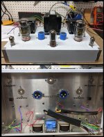
Finally got everything I needed to start my build about a week or so ago. Has been a little slow going but after agonizing on the layout, all the major components are located except for the big input filter cap which I'm planning to put under the PT with a 3d printed saddle to hold it. Hopefully just a handful more tiny holes to drill and also am contemplating how I can stiffen up this hammond chassis. It's very flexy. Last time I'll use one for a project like this.
Decided to deviate a little from the kegger/blueglow/abdellah schematic, but not really. Ended up dividing L from R entirely after the first capacitor, so only using half of the ECC85's (cringe) but also wiring the L/R to use different halves so I can swap the tubes every ~year to "evenly" wear them. Also using a single DPDT per KT88 so I dont have to run those wires all over the chassis. Should make for a much cleaner build. Hard part now is deciding what color to paint it!
Thanks again to everyone for the advice and encouragement to do this. Will come back at the end of the build with another update with hopefully with nothing but good news. (fingers crossed)
Attachments
Closing out the thread
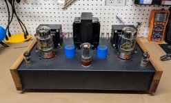
Final update here if anyone still cares, but wanted to say thanks for the advice and general guidance here for those who participated.
Generally pleased with how it came out for my first build from a schematic. The hammond chassis is the last one I'll ever use for a project with this size of iron, it's just too thin and flexy. There were a couple of times I almost chucked it in the recycle bin to be honest, but the stiffening braces really did the trick even if it did make layout a little more challenging in areas.
On the circuit side, no issues at all, the big B+ voltages are a little low (~10-50V) from where Mark has them, but I do have a thermistor, backup diodes, different input cap, chokes & OT's with a higher dc resistance, and bleeder resistors. Also, this was expected and desired since the OP is a little more reasonable on the KT88's now around 78-80mA and 30W Pd. Believe his schematic has it around 82mA/33-34W.
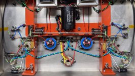
The ECC85's are spot on around 220-230V at the plates and 2.62V at the cathodes. Oh, and it's dead quiet. Arguably quieter than the solid state aleph which has a little hum in one channel that can only be heard 1" from the tweeter cone. The KT88 has none in either. Sigh of relief for sure! Have very limited listening in it right now since it was only hooked up late last night, but initial impressions are good. Anyway, couple of pictures of the completed result.
Final update here if anyone still cares, but wanted to say thanks for the advice and general guidance here for those who participated.
Generally pleased with how it came out for my first build from a schematic. The hammond chassis is the last one I'll ever use for a project with this size of iron, it's just too thin and flexy. There were a couple of times I almost chucked it in the recycle bin to be honest, but the stiffening braces really did the trick even if it did make layout a little more challenging in areas.
On the circuit side, no issues at all, the big B+ voltages are a little low (~10-50V) from where Mark has them, but I do have a thermistor, backup diodes, different input cap, chokes & OT's with a higher dc resistance, and bleeder resistors. Also, this was expected and desired since the OP is a little more reasonable on the KT88's now around 78-80mA and 30W Pd. Believe his schematic has it around 82mA/33-34W.
The ECC85's are spot on around 220-230V at the plates and 2.62V at the cathodes. Oh, and it's dead quiet. Arguably quieter than the solid state aleph which has a little hum in one channel that can only be heard 1" from the tweeter cone. The KT88 has none in either. Sigh of relief for sure! Have very limited listening in it right now since it was only hooked up late last night, but initial impressions are good. Anyway, couple of pictures of the completed result.
Attachments
That's really nice! Four months from first post to last, you did a good job not just spinning your wheels talking about making your amplifier- you took your cut and moved on.
I can't say my builds look that clean, you have experience doing electronic and metal fab?
It surely sounds as good as it looks!!
I can't say my builds look that clean, you have experience doing electronic and metal fab?
It surely sounds as good as it looks!!
Thanks, Duke58! I tend to take a long time to make a decision but then move quickly when I do.
I have a lot of metal fab experience with sheet metal, machining (mills, lathes, hand tools, etc), welding, and cutting but is electronics as a hobby or skill is totally new to me. Technically you could call this the 3rd full electronical project I've ever done and the first where I had to read/understand a schematic and make the physical circuit. The prior were just "put this component there" without understanding fully what or why. The aleph j had a little more free form when it came to final wiring, but even that was pretty straight-forward.
One of the reasons I undertook this project was to try to learn a few of the things I didnt feel like learning when at school for a mechanical degree. Definitely learned/re-learned a good bit but still very much a work in progress there!
@Pechelman-- your soldering skills look great, it's all neatly arranged-- makes it look like you've been building amplifiers/electronic projects like a pro.
I'm also an ME, was an electronics tech when I enlisted in the Marine Corps in order to get out of my parent's house one week after graduating high school. Last thing my stepfather said when I was getting into the recruiters van at zero dark thirty in the morning was "what would happen if I didn't work for a week?" I was getting into the van and turned around and said, I don't know, try it.
The next stupid thing someone said was the Marine Corps Drill Instructor getting on the bus at MCRD and saying - whoever is on this bus reporting to MCRD, get off the bus and stand on the yellow footprints. I turned around to see if there were any stragglers who got on the wrong bus.
Gonna go listen to some music and have a beer now...
- Status
- This old topic is closed. If you want to reopen this topic, contact a moderator using the "Report Post" button.
- Home
- Amplifiers
- Tubes / Valves
- General advice for first full diy