This is going to be my first thread on DIYAudio in ten years of being almost a daily reader. Better late than never!
My last project completes the 'family' of home amplification projects built with Static Induction Transistors: single-ended and push-pull amplifier and phono amplifier. These are mostly Soviet times devices and they are still more or less available on ebay. My background is from that part of the world so I also got options of buying from local vendors. Phono amplifier also uses Japanese SITs.
My passion in DIY audio is also transformer signalling and I also had a few chances to prove its advantages in industrial hardware design.
I have to say that I am not big fan of NFB and the push-pull amplifier is the only one which employs NFB. My excuse is it has been chosen so based on listening tests and therefore it is objective. At least for me") , obviously.
, obviously.
So, the push-pull amplifier is called Mriya PP. Before the schematics of the amplifier got finalized, there were a few months of listening to a prototype so almost all of the decisions on components and values have been driven by listening experience. Not just mine - my wife has a perfect ear for music and with time I learned (painfully) that my engineering reasoning is not always the way things should be.... Now she also states that Mriya PP sounds above everything else I made before and that includes some decent designs like the SV811 SE amplifier, for example.
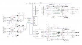
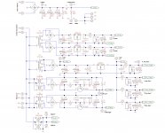
The signal circuit is quite basic: the input transformer (Cinemag) drives the tube loaded with phase splitting transformer (Lundahl). The driver stage is is powered in inverted way - the cathode of 6N6P is fed with stabilized -120V and the top terminal of the transformer by DC is at ground potential through serial resistor of 47Ohm and the ohmic resistance of the output transformer secondary. The phase splitter drives a matched pair of KP802A SITs. The output transformer (Toroidy) is connected to the push-pull output stage in the way the signal on the secondary comes to the phase splitter in phase with the plate voltage. It is not exactly the 'error correction' NFB but I guess it is the closest term for this particular feedback configuration.
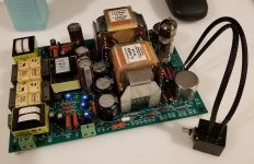
The power supply for the amplifier is a busier part of the design but it is how I typically approach it - between the choice of a separate power circuit and creating the bias/rail on the spot I chose the first option. I like the ubiquitous 78/79 series of voltage stabilizers for bias generation as these are very good on noise.
The idle current of KP802A is set at 50mA. These things are very stable thermally so there is no need to employ any monitoring of the operating point.
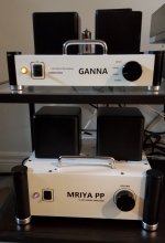
The speakers are DIY (not mine) Pencils with Alpair 10p drivers designed and built by one of the regulars at DIY and they are really impressive. I had a crush on Zu Audio speakers but when these red beauties showed up in our house, I really do not have good arguments to my wife for why we should upgrade... For her the speakers should just sound great and this is what they are doing.
And about the sound itself. It is very open, light and transparent, there is no fatigue whatsoever. My music sources are high resolution digital recordings played through DIY GANNA DAC (2x PCM1704 differentially on Sowter 9055 transformer and 6N6P with Sowter line driver transformer at the output) and a NAD turntable.
My last project completes the 'family' of home amplification projects built with Static Induction Transistors: single-ended and push-pull amplifier and phono amplifier. These are mostly Soviet times devices and they are still more or less available on ebay. My background is from that part of the world so I also got options of buying from local vendors. Phono amplifier also uses Japanese SITs.
My passion in DIY audio is also transformer signalling and I also had a few chances to prove its advantages in industrial hardware design.
I have to say that I am not big fan of NFB and the push-pull amplifier is the only one which employs NFB. My excuse is it has been chosen so based on listening tests and therefore it is objective. At least for me
, obviously.So, the push-pull amplifier is called Mriya PP. Before the schematics of the amplifier got finalized, there were a few months of listening to a prototype so almost all of the decisions on components and values have been driven by listening experience. Not just mine - my wife has a perfect ear for music and with time I learned (painfully) that my engineering reasoning is not always the way things should be.... Now she also states that Mriya PP sounds above everything else I made before and that includes some decent designs like the SV811 SE amplifier, for example.
The signal circuit is quite basic: the input transformer (Cinemag) drives the tube loaded with phase splitting transformer (Lundahl). The driver stage is is powered in inverted way - the cathode of 6N6P is fed with stabilized -120V and the top terminal of the transformer by DC is at ground potential through serial resistor of 47Ohm and the ohmic resistance of the output transformer secondary. The phase splitter drives a matched pair of KP802A SITs. The output transformer (Toroidy) is connected to the push-pull output stage in the way the signal on the secondary comes to the phase splitter in phase with the plate voltage. It is not exactly the 'error correction' NFB but I guess it is the closest term for this particular feedback configuration.
The power supply for the amplifier is a busier part of the design but it is how I typically approach it - between the choice of a separate power circuit and creating the bias/rail on the spot I chose the first option. I like the ubiquitous 78/79 series of voltage stabilizers for bias generation as these are very good on noise.
The idle current of KP802A is set at 50mA. These things are very stable thermally so there is no need to employ any monitoring of the operating point.
The speakers are DIY (not mine) Pencils with Alpair 10p drivers designed and built by one of the regulars at DIY and they are really impressive. I had a crush on Zu Audio speakers but when these red beauties showed up in our house, I really do not have good arguments to my wife for why we should upgrade...
For her the speakers should just sound great and this is what they are doing. And about the sound itself. It is very open, light and transparent, there is no fatigue whatsoever. My music sources are high resolution digital recordings played through DIY GANNA DAC (2x PCM1704 differentially on Sowter 9055 transformer and 6N6P with Sowter line driver transformer at the output) and a NAD turntable.
Attachments
Last edited:
Very cool !
So the feedback goes to the otherwise grounded end of the driver transformer - I first saw this in a NP design and think it’s very clever still.
What values (approx) did you decide on For R1/R2 (R13/R14) ? I Guess at a minimum you just use some value for R1 ?
Really classy and professional build congratulations)
So the feedback goes to the otherwise grounded end of the driver transformer - I first saw this in a NP design and think it’s very clever still.
What values (approx) did you decide on For R1/R2 (R13/R14) ? I Guess at a minimum you just use some value for R1 ?
Really classy and professional build congratulations
)Very cool !
What values (approx) did you decide on For R1/R2 (R13/R14) ? )
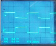
R1 = NU, R2 = 0R. The key changes were R6,R7 = NU, R5,R8 = 7K5. These got changed after I got the toroid output transformer as a measure to manage the bandwidths of phase splitter vs. output in the way the flat frequency response is achieved. This type of feedback may become a positive one at some extreme point. If it is managed right, there is a very good stability om sharp transitions, like shown below (ignore the phase reversal). The output is the bottom trace.
Attachments
Are you building and selling these ? I’ve been wanting a affordable phono tube pre for sometime now
Thank you for asking!
No, it is a passion of mine, there is no way I could charge for the amount of time I spent on those. I got spare PCBs for all of the designs but the PP amplifier had some major mods on the power section so this one is not that usable. Just check the pinout on that 229A88, somebody still can't forget how the cylinders are fired in a 4-cylinder engine!How deep is the NFB? <10db? With two transformers within the loop were there any issues?
About 12 dB
That's one cool amp, congrats!
And it has a nice name
This SIT journey started for me before Canada and that was a dream of mine to execute on those ideas this technology inspired.
With two transformers within the loop were there any issues?
Until I tried the toroid output, I had this suspicion that it is not going to work well. I tested it with Hammond PP transformers and that showed very good middle range but above 10kHz the things were very messy. No oscillations have been ever observed, though.
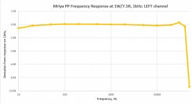
I guess almost all of the guys who are making toroids in the world now are basically repeating the same design and all of them are really fast. Returning the signal back to the driver should introduce minimal phase shift as well and toroids do it really well. My signal generator stumbles at frequencies below 10Hz so I do not know what is the -3dB frequency for bass, it is -0.5dB at 10Hz. It is my understanding that the high frequency cut-off just follows the 1660S. See attached a quick measurement result on frequency response. -3dB on highs is at app. 43kHz.
Attachments
I did some additional measurements today.
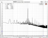
Output impedance = 0.9R
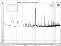
Also, here is a spectrum content for PP amplifier at 0.5W and 2W output power (2W is taken with voltage divider so the peak value is not reflecting actual higher power). As in Scarlett Solo 3rd the output are balanced, I was not able to go higher in output power for this kind of measurements as I do not have proper cabling yet. I used the signal generator from REW software and Solo analog output.
I think the trend is quite clear: at low power the output signature is resembling the SE as idle current is meaningful. When amplifier gets into AB regime, again, the expected changes to the spectral content happen.
It does look like I am apparently the '3rd harmonic' guy as I do put the sound quality of my SIT PP amplifier above the SIT SE. In most of musical genres
But overall, the numbers are pretty mediocre so nothing to boast about, I guess. But I know the numbers now, which is what I always wanted
Output impedance = 0.9R
Also, here is a spectrum content for PP amplifier at 0.5W and 2W output power (2W is taken with voltage divider so the peak value is not reflecting actual higher power). As in Scarlett Solo 3rd the output are balanced, I was not able to go higher in output power for this kind of measurements as I do not have proper cabling yet. I used the signal generator from REW software and Solo analog output.
I think the trend is quite clear: at low power the output signature is resembling the SE as idle current is meaningful. When amplifier gets into AB regime, again, the expected changes to the spectral content happen.
It does look like I am apparently the '3rd harmonic' guy as I do put the sound quality of my SIT PP amplifier above the SIT SE. In most of musical genres
But overall, the numbers are pretty mediocre so nothing to boast about, I guess. But I know the numbers now, which is what I always wanted
Attachments
Last edited:
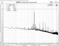
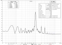
My learning curve on Scarlett Solo is still climbing up and I found better ways of using this truly remarkable little device. Today I looked into optimizing the spectral content of distortions vs. idle current. As a result, the idle current is set at 75mA per SIT. The spectrum started looking a bit more civilized. But the sound has not changed even a bit!
I used smoothing in REW as with not stabilized power rail the spectrum has a lot of spikes from amplitude modulation of the main tone and harmonics. Here is how things are at 1.2W of output power into 7.5Ohm of active load. A very nice thing is the same grid of the harmonics stays in the same relation when the power goes up/down. The observation from the first paragraph does not really support the statement but it may be at least partially the reason it sounds so pleasant and clean to the ear.
I used smoothing in REW as with not stabilized power rail the spectrum has a lot of spikes from amplitude modulation of the main tone and harmonics. Here is how things are at 1.2W of output power into 7.5Ohm of active load. A very nice thing is the same grid of the harmonics stays in the same relation when the power goes up/down. The observation from the first paragraph does not really support the statement but it may be at least partially the reason it sounds so pleasant and clean to the ear.
Attachments
Last edited:
- Status
- This old topic is closed. If you want to reopen this topic, contact a moderator using the "Report Post" button.
- Home
- Amplifiers
- Tubes / Valves
- Push-pull SIT amplifier