I noticed this designer doesn't like grid leak resistors
I mean, he has 1K grid leak resistors on the output tubes. I guess that would mean he really likes grid leak resistors? Is that actually what's in the product (I sincerely hope not!)
Windcrest77,
As I said, I was referring to the schematic Link in Post # 12 of this Thread.
By the way, speaker sensitivity is an odd concept (at least many speaker marketing people do some odd things, and abuse the privilege when they specify speaker sensitivity).
Which is more sensitive?:
An 8 Ohm speaker that never drops below 8 Ohms, and produces 92dB @ 2.83Vrms (1 Watt into 8 Ohms), at 1 Meter.
OR,
A 4 Ohm speaker that drops down to 2 Ohms, and produces 94dB @ 2.83Vrms, at 1 Meter.
The 8 Ohm speaker wins hands down, whether your amplifier output has multiple tap output impedances or not.
The 8 Ohm example has more sound, lower amp distortion, etc.
Resistors that are in series from the signal to the grid, are grid stopper resistors.
Resistors that come from the signal, and connect to ground are the grid leak resistors.
Look again at the circuit on the link in Post # 12.
All the grids in that schematic have both grid stopper resistors, and grid leak resistors (but the volume control pots are the grid leak resistors for the input tubes).
Safety First!
Sometimes the output transformer primary shorts to the secondary. Floating secondaries have been known to cause electric shock (not often, but it only takes once).
Ground the common terminal of the output transformer.
I once had a brand new output transformer that had a short from the primary to the laminations. That could have been a shocker.
Be sure to ground the end bells and / or the laminations to the chassis as appropriate.
Last edited:
I mean, he has 1K grid leak resistors on the output tubes. I guess that would mean he really likes grid leak resistors? Is that actually what's in the product (I sincerely hope not!)
I am very suspect of that scheme, I'm going with the 2011 version! The schematics found are all for the ZKIT I have yet to find the main product scheme. The ZKIT Is an experiment board with silicon diodes. I'll use a tube rectifier. Hopefully the ZKIT is close enough to the commercial amp.
Last edited:
Windcrest77,
As I said, I was referring to the schematic Link in Post # 12 of this Thread.
Safety First!
I see, yes the 2011 version looks much less in error. I've seen so many Zen schemes since last night I swear I saw one with no grid leaks! We're outside sitting on the swing in the backyard right now drinking mohitos, cool to be semi live with you guys!
Many people have never done the following:
1. Measure the DCR of their loudspeaker with an Ohmmeter.
Often the speaker has impedance at very low frequencies that are the same as the DCR.
Often the speaker has impedance at mid frequencies somewhere in the range of about
200Hz to 500Hz that are also the same as the DCR.
2. Use a scope to measure the peak voltages on the loudspeaker when they are listening to music at the level(s) that they typically use.
((Peak Voltage)squared)/(Impedance x 2) = RMS power (or reactive "power" at frequencies where the speaker is reactive).
Use the peak voltage, and the speaker DCR to calculate what is probably the highest power you are putting into the loudspeaker when you listen to it.
The above often surprises people when they get around to doing # 1. and # 2. above.
Last edited:
If you want to build a sketchy version of the Zen amp, you could build a sketchy preamp to go with it.I see, yes the 2011 version looks much less in error.
Attachments
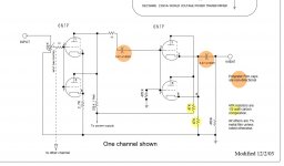
Unfortunately, the parallel cathode follower output has an un-bypassed 47k plate resistor.
Sketchy, yes.
47K/mu = 47000/20 = 2350 Ohms.
That 2350 Ohms is in series with 1/Gm.
1/Gm = 1/2200microMhos = 455 Ohms. 2 cathodes in parallel gives 227 Ohms.
The output impedance is 2350 + 227 = 2577 Ohms.
That is probably much higher than you were shooting for.
So, bypass the 47k plate load with a proper bypass cap.
I will not spend more time looking for errors on this schematic.
Last edited:
I will not spend more time looking for errors on this schematic.
It's A Decware product, not mine! It just reminded me of how strange the schematic was at the start of this thread.
audiowize,
I knew that was just a link, and not your circuit.
The web is full of strange schematics.
Some have un-intentional errors (typo, omissions, wrong connections, etc.).
I even do that too.
Some have never been built, have never been tested, or have been completely abandoned.
Caveat Emptor.
User Beware.
Windcrest,
I would take 6A3Summer and Audiowize’s advice! Having reviewed Decware’s schematics in the past, they made me pause for all the reasons they mentioned.
Honestly, a good review of the basics is important. One can get that from numerous vacuum tube books and from the Valve Wizard website.
In addition, if you want a good fleshed out, thoroughly explained EL84 SET design, look here:
Exordium | Analog Ethos
Analog Ethos also has an EL34 SET with equally great diagrams and explanations.
Strongly recommended.
Best,
Anand.
TonyTecson,
I apologize.
I stand corrected.
Lots of 6BQ5 data sheets say Pentode.
But some 6BQ5 data sheets say Beam Power.
And lots of data sheets say 6BQ5/EL84.
I wish I could find some really original data sheets, I really believe the 6BQ5 started out as a Beam Power tube.
I believe that decades ago it was all about patents. In order to not infringe, a tube was designed that used Beam Formers, but with identical specifications, to sell them as a replacement (and get around the design of tubes that used suppressor grids).
I think this was an International issue.
poseidonsvoice,
Nice set of amplifiers.
The EL84 amp gives the choice of Triode wired or Ultra Linear connection.
I am not sure if the output transformers that Windcrest77 already owns have Ultra Linear taps or not.
All these projects, and so little time.
My first amplifier (1962?) was a Mono Knight Kit EL84 Push Pull amp (in pentode mode), with 12AX7 phono stage, and a 12AU7 line stage and concertina splitter.
Last edited:
You should definitely *not* use the same cathode resistor for both channels. This will absolutely cause channel separation issues. In the last amp I had in for service that had a shared cathode resistor in the output stage, I saw only 40dB of channel separation. I was not Inspired.
I see what you did there
") .
.I had a stereo amp with 45 output tubes.
The channel separation was 40 dB at all frequencies.
It takes a very good phono cartridge, with almost perfect alignment to get 35 or even 30 dB of channel separation, and that is only at mid frequencies.
I do not remember anybody in a listening group that complained about the sound of the cartridge's channel separation.
... I have yet to find the main product scheme.
The last page of this manual maybe?
https://www.decware.com/Select/select_ownersmanual.pdf
Mike
Klipsch Reference Premiere RP-600M loudspeaker Measurements | Stereophile.com
The big take away from that is the impedance curve:
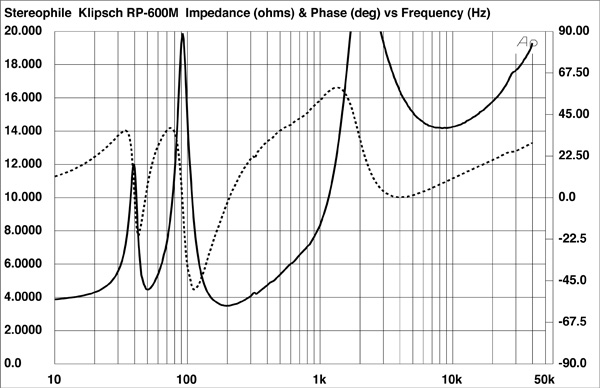
The very non-flat impedance response will play havoc with any high output impedance amplifier — like the Decware. That alone makes it “not recommended” for this application.
dave
Why am I not surprised?
An "8 Ohm" loudspeaker that dips to about 3.5 Ohms.
But, I would not be so sure that it could not please the listener when it
was driven by the Decware amplifier.
The gain of the Decware will go down when driving 3.5 Ohms.
But the gain of the output stage will never be higher than 20, no matter what load is presented to it (Gain max = mu, the outputs are in Triode Wired mode).
How many of you have ever done experiments with a loudspeaker and amplifier
and connected a 4, 8, or 15 Ohm resistor in series, just to hear the modification of the sound from the system?
Oh, who is to say that one reason the Decware pleases some listeners is that it
does have medium channel separation; it does not have high channel separation?
I never noticed the medium channel separation when I heard the original Decware amp.
However, again, there was no bleeder resistor, and no voltage divider resistors across the two 20uF caps that are in series. At least use a couple of 100k resistors that will divide the DC voltage across those 20uf caps, and after power-down, eventually will bleed the B+ down too.
- Home
- Amplifiers
- Tubes / Valves
- Some quick questions on Zen Decware EL84 SET schematic