Hi,
Just found this diagram in the Japanese schematics and designs published today on this forum.
I guess it could be used too for using the ultralinear tap to feed G2 with a somewhat lower voltage than B+. For example use a KT88 with 560 VDC B+ and 400 VDC for G2. G2 could still follow the plate’s swing.
Has anyone tried this ore something similar? What can be expected?
Regards, Gerrit
Attachments
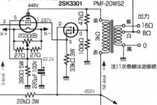
I'm sure that this circuit would work, especially with a TV sweep tube or other tube that likes a low screen voltage. The screen voltage in this circuit will always be less than the plate voltage, and quite low when the plate is pulled toward the cathode due to the voltage divider tied to ground. One can tie the ground end of the divider to B+, but that can create it's own isssues.
There has been considerable discussion and experimentation with variations on this concept scattered throughout this forum. One thread is here:
Adjustable distributed load discussion
I have since wandered into a different way of doing this which is just beginning to come to fruition:
Variable Triode-Ultralinear-Pentode modes?
UNSET is coming?
The technique can be made to work if the voltage ratings of the Mosfet can be contained and the tube g2 max voltage rating obeyed.
Dividing the plate voltage down with the R divider for a lower g2 voltage will increase the effective triode Mu above the intermal value and raise the triode's plate resistance too. Not generally desirable for an efficient power tube. Power output is greatly reduced with the g2 Volts dropped severely when maximum current is called for. Many TV Sweep tube internal triodes also have 2nd harmonic roll-over in their curves, which the simple R divider UL scheme does not fix.
-------------------------------------------------
Using some "shunt Schade" N Fdbk can get you a better effective triode, since the plate resistance goes down (effective triode Mu goes down too). The g2 voltage can then be set for optimum power output at max plate current too. Making the tube more efficient for power use. The 2nd harmonic rollover in the triode curves gets improved too with "shunt Schade" N Fdbk.
However, then you have a low impedance point to drive with a current source for input.
Another less obvious distortion problem shows up with the "shunt Schade" scheme due to the N Fdbk resistor current being proportional to Vplate - Vgrid, instead of just Vplate. This can be a problem with low gm tubes where the grid drive V can be significant. (grid 1 tends to be near a square law transfer for power tubes, so the grid1 V tends to be proportional to the SQRT of Vplate for a presumed linear output)
Putting a P channel Mosfet cascode stage in series with the "shunt Schade" N Fdbk resistor can fix the grid1 V interference, changing the N Fdbk to a modulated current source, proportional only to plate V.
I've been playing with a variant of this "corrected Schade" scheme that puts the P Mosfet in a different position to isolate the grid1 V from the N Fdbk, and provides a high input Z. Still in progress.
---------------------------------------------------------------
Probably some circuit trick(s) could be applied to the original above posted attenuated UL scheme too, to improve that. Will be interesting to see what George has come up with there.
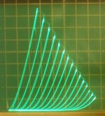
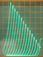
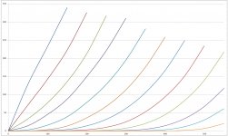
Here are some "triode" pics for the 21HB5A TV ($1) Sweep tube, using different techniques.
All are 50V/div Horiz. and 50 mA/div Vert.
1) triode mode (g2 conn. to plate), 5V steps (the ultra-linear/Mosfet scheme will normally give the same shape curves as triode mode, just higher Rp.)
2) Corrected shunt Schade, 6.25V steps
3) normal shunt Schade (old pic, no data)
Notice the lack of "roll-over" or distortions in the Corrected shunt Schade.
That's 1/2 an Amp at the screen top. Try getting that with a 211 and 350V B+.
Corrected Schade uses the same electrode (grid1 to cathode) for both N Feedback from the plate, and the Hi-Z input drive. Without Vg1 getting into the N Fdbk current.
Even a DHT has some distortion from the g1 transfer not quite matching the plate (or g2) transfer function. Later, higher gm tubes have a greater mis-match between g1 and g2 leading to obvious "roll-over" in their "triode" curves.
Corrected shunt Schade fixes that completely, even for $1 beam pentodes. And has a hi-Z input with good sensitivity.
DHTs are HISTORY
Attachments
Last edited:
You can also use an emitter follower as well as a MOSFET although the base resistors would have to be lower. You could use a cathode follower too. I think your idea would work well with a KT88. I was thinking of the same thing with a PP output stage. If you want a different g2 voltage and/or tap ratio you can add a third resistor from the base/gate to HT - so you have three resistors one to plate one to HT and one to ground from the gate of the MOSFET.
Last edited:
Hi smoking-amp, can I ask you a sketch of it to perform some simulations? ThanksPutting a P channel Mosfet cascode stage in series with the "shunt Schade" N Fdbk resistor can fix the grid1 V interference, changing the N Fdbk to a modulated current source, proportional only to plate V.
can I ask you a sketch of it to perform some simulations? Thanks
Putting a P channel Mosfet cascode stage in series with the "shunt Schade" N Fdbk resistor can fix the grid1 V interference, changing the N Fdbk to a modulated current source, proportional only to plate V.
My flat bed scanner is down at the moment, but I will start a thread on this in a week or two. (have to do taxes yet! was hoping Covid 19 might take out the IRS, but no such luck)
First, a brief history of how this developed. I was following the thread below by SpreadSpectrum using "shunt Schade" using an Op Amp V to I driver:
Shunt Feedback 6384 SE Amp
The irreducible distortion that remained led me to consider if conventional "shunt Schade" maybe had some "bug" hiding in it. And I soon realized that it does.
As mentioned above, the input Vgrid1 corrupts the current through the shunt plate N feedback resistor. I = (Vplate - Vgrid1)/ R. Especially for a low gm tube with large grid1 V swing.
So the 1st version I tried was to put a P-channel Mosfet cascode stage in series with the feedback resistor. This just uses a P Mosfet with Source connected to the bottom of the feedback resistor, and the Drain connected to Grid1, with a second Schade divider resistor from grid1 to a minus biased V signal source ( to get the grid1 voltage into a normal bias range.) -Or- use a current source driver from some -V up to grid1 as is typical for "shunt Schade" (with enough idle current to get the grid V into the -Vbias operating range.). Then a fixed voltage of roughly +25V on the Mosfet Gate for cascode use, with some Gate to Source Zener protection for start-up. The Mosfet cascode stage still puts out the same feedback current regardless of what voltage the grid 1 has on it. So this eliminates the drive signal polluting the N feedback signal. The sum still obtains at the grid 1 of course.
(I used some variable power supplies for all this, so voltages are estimated)
This worked well to fix the plate curves, but this still has a low drive signal input impedance.
---------------------------------------------------------------------------------------------------------------------------------------------
With a Mosfet in the parts list now, I then thought if there might be some way to get a high input impedance as well. Driving the Mosfet gate with the input V signal unfortunately gets one back to Vplate - Vgrid for the feedback current. So that was out.
Then a stroke of "genius" struck. Why not just make it a -series- Schade by putting the P - channel Mosfet under the tube cathode as a follower (source terminal to cathode). So now the input signal goes thru a P - channel follower to drive the cathode.
The old "shunt Schade" feedback, via the resistor from the plate, can just go directly to the grid1 now, since no input drive signal V appears at grid1. A divider resistor from grid1 to some negative V (like -100V) forms a voltage divider for the grid1 N feedback. (the minus V adjusted to get grid 1 into a normal operating bias range) The P-channel Mosfet follower has the same or similar neg. V on it's drain for its operating range.
So this ends up operating just like series Schade N feedback, except an R attenuator is used, instead of the interstage xfmr in Schade's paper, to develop the grid1 feedback V. Note that the tube is now non-inverting. Input signal impedance to the P-channel Mosfet follower is a high Z. And the P-channel Mosfet does not require a particularly high voltage part, just sufficient V to handle the usual input grid voltage swing safely (now appearing on the cathode). The tube transconductance, being much lower than that of the Mosfet follower, sets the tube operating current versus input signal V still, so this should still sound like a tube.
Some interesting advantages gained are that the tube now gets effectively -increased- plate V and -increased- screen V when delivering maximum current. (via added cathode V) You'll notice the above "triode" curves pic can deliver decent current at low plate V, better than most triodes. (in fact, equal to the hidden pentode used)
I'll be curve tracing some other TV Sweep tubes using this scheme next week or so and posting a thread and schematics. Eventually a SE "triode" amplifier and then a P-P version will be tried to check sound quality. The plate curves do look nice.
Last edited:
Will be interesting to see what George has come up with there.
Then a stroke of "genius" struck. Why not just make it a -series- Schade by putting the P - channel Mosfet under the tube cathode.
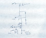
You figured it out. Tie the control grid directly to as positive voltage source bypassed to ground for a simple version of "crazy/dual drive." The screen can be tied to a bypassed fixed voltage source, which can be 150 to 200 volts for sweep tubes, and full B+ for tubes like a 6550, or anywhere in between.
Since both grids are fixed, and the cathode is driven, this works like dual grid drive. For something more triode like, the "Schade" feedback can be done with a resistor directly from plate to control grid with another resistor from grid to ground. The ratio of these resistors determines the amount of "triodness." The tube current is adjusted by applying a POSITIVE voltage to the mosfet's gate. More positive makes less tube current.
Now it is possible to make a complete fixed bias tube amp without a negative voltage supply. Yes the cathode sits at a positive voltage as in a conventional cathode bias scheme, but this voltage is not "wasted" since the voltage across the tube increases as the tube is driven further into conduction. The mosfet's source goes to very near zero (millivolts) as does the cathode.
I made a board almost 10 years ago with a mosfet on every element of a TV sweep tube except the plate. It has been the subject of several experiments over the years, most ending in frustration usually because I succeeded in making some excellent TV jammers or turned mosfets to dust and even made two 6HJ5's explode violently.
I got a Vacuutrace about 4 years ago which helped, but actually delayed the cathode drive experiments since it can not step the "grid" voltage positive. This may be an issue with your curve tracer too.
The only disadvantage to this technology is that real bad things happen when the mosfet shorts and the sweep tube tries to suck 5 amps of plate current from a power supply with 1000uF of output capacitance set at 500 volts. That makes 6HJ5's explode!
Many P channel mosfets have a limited SOA and tend to fail to a short. If you choose to play with this tech, start with a Fairchild / On Semi FQPF925. They live in the cathode of a 36LW6 making 30 WPC in SE on 550 volts into 2500 ohms. Set the grid resistor ratio to about 11 to 1 (300K grid to plate, 30K grid to ground). I use 175 volts on G2. I have had this combo to 40 watts audio output, but the 36LW6 was eating about 85 watts at idle and was very mad....red faced kinda mad!
This circuit results in nice triode curves from a TV sweep tube with 500 volts on it's plate and 175 on its screen. I have called this a Composite Electron Device, and I have three working amp designs operational using it.
I have had to trace the curves manually with adjustable power supplies since the Vacuutrace can't do positive voltage steps. The CED simulates well in LT spice, but all voltages are IN PHASE so it takes a bit of getting used to. It works well for low level stages too, and G2 in the driver can be used for some additional negative feedback input in a Push Pull amp.
The UNSET amp that I have been working on uses a small high Gm pentode driving a big TV sweep tube. Both are set up using the CED to emulate triodes in a SE Triode design, but no triodes are used in the amp, hence the term UN SET. The final prototype version is being built now, and if there are no issues, I will order a batch of boards and it will be the next Tubelab board.
The CED does NOT work in an LTP stage since no phase inversion takes place. This makes an all CED push pull amp a bit more complicated....or not.
I have done several different circuits, some that work better than others, but the best design so far is a CED input stage for voltage gain a split load phase inverter using a mosfet, and a pair of CED's in push pull for output. Three tubes per channel, making 75 watts from $3 worth of tubes!
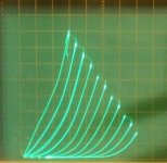
Included is the basic CED schematic. Pretty simple, but works. The curves are from a $1 6GF5 wired as a CED. The uneven spacing is due to my hand turning the power supply voltages on the gate terminal. The steps are positive with zero volts being max current (blue line) and step size is 5 volts.
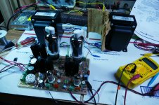
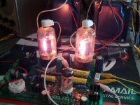
The board is a prototype UNSET amp. Some more info and test data is here:
UNSET is coming?
Attachments
Last edited:
Very cool. I've been wondering what it was.
It's a bit like setting the feedback ratio in my p-channel follower driven amp. My experience there was that setting it for over 30% feedback starts requiring big supply voltages to get the bias right. Of course, a cap can help but I don't like extra time constants in the feedback unless I have to. (Plus then you have a bias resistor stealing current from your feedback network again.)
It's a bit like setting the feedback ratio in my p-channel follower driven amp. My experience there was that setting it for over 30% feedback starts requiring big supply voltages to get the bias right. Of course, a cap can help but I don't like extra time constants in the feedback unless I have to. (Plus then you have a bias resistor stealing current from your feedback network again.)
Well I'll be doggone.
Must be something to that saying "all great minds think alike" after all.
Interesting that we arrived at the same circuit (other than some minor DC level shifts) from completely different angles. I would never have guessed there was a problem with typical "shunt Schade" until SpreadSpectrum did his design. Basically the same circuit is used for inverting Op Amps all the time, but they have huge gains, so input V swing pollution is not an issue. Single stage tube gain however is another matter, and requires some re-thinking. Shifting to a series Schade topology to get high input Z then struck the same Gold George found.
None of this would have been inspired without the $1 tube sales years back. Trying to get that Golden sound using one of those cheap $1 tubes. So Hats off to the original $1 tube list vendors. Innovation drivers. I've enjoyed the journey.
Hope Stan is still tuning in from up there. Although I wonder if he took all the DHT tubes with him and left the TV Sweeps behind !!!
Last edited:
None of this would have been inspired without the $1 tube sales years back.
The real fun started here, when AES decided to get out of the NOS tube business, over 11 years ago:
Tube sale at AES
Screen drive and other P-P experiments
Just as this feeding frenzy was dying out another popular tube seller called it quits (Angela instruments maybe?). VacuumTubes.Net bought them out, and blew out big lots of tubes for well UNDER $1 each. I wound up with over 100 6BQ6 types for an average price in the 65 cent range...one of the ugliest pairs have been seen operating in the white glow region. Yes, you can get 20+ watts of SE audio out of a 65 cent tube...for about 20 minutes. It sounded pretty good until one of the tubes flashed into a bright blue cloud.
The remaining overstock prompted the VacuumTubes.Net $1 list, which was countered by Stan at ESRC.
Although I wonder if he took all the DHT tubes with him and left the TV Sweeps behind !!!
I visited his place last December during a trip to Disney World with 4 grandkids and family. I didn't have room in my van to bring back a large stash of tubes, so I left a stash of about 400 tubes in a corner of his warehouse. Stan was going to bring them to the Dayton Hamfest for me. It turns out that the hamfest never happened and Stan was already gone by hamfest time. There were over 100 undiscovered sweep tubes in that box that were capable of making over 200 watts per pair, and 100 each of $1 TV IF amp tubes that work well in the CED design as drivers.
The CED and it's UNSET and big P-P applications were the work of countless hours of thinking, tinkering, and blowing stuff up. It's the result of taking an idea and beating on it until it becomes something useful.
I have one more "big idea" in the vacuum tube world, and like the CED it's been a long work in process. This one started out a bit further back in time. It was an offshoot from my work in high efficiency, high linearity RF power amplifier work at Motorola in the early 2000's when the cell tower operators were spending millions of dollars per month for electrical power.
This thread led me to some patents issued to Ross MacDonald in the 1950's for vacuum tube cathode follower circuits that found their way into Tektronix scopes and other low level circuits. By the end of the thread I had given one of those designs the Tubelab treatment and squeezed 30 watts out of it.
augmented cathode follower?
Why use a cathode follower in the output stage, drive levels need to be HUGE? Yes, but a cathode follower has a very high PSSR (power supply rejection ratio). It doesn't care what the supply voltage is doing, or how noisy it is, as long as there is enough supply voltage to avoid clipping.
We can built an agile power supply whose output voltage can be adjusted on the fly to feed the output stage just enough voltage to avoid clipping, but not too much to just be burnt off as heat. This was the principle behind my high efficiency RF amps, and is the basis of the emitter follower designs used in class G and class H solid state amps.
I had all of this working in 2007 and published the magazine article in Circuit Cellar magazine in 2009. That article has vanished from their web site, so I include it here.
Since then I have been working on the design with some excellent results in the mind of the simulator....a real parts build is underway. WHY?
I have all of the parts needed to build a 1KW tube amp. I am 67 years old. If I built this amp using conventional technology I would not be physically able to move it, and powering it from a conventional US spec power outlet (1800 watts max) would be iffy. I need to make it efficient to reduce the number of output tubes, and I need a creative power supply, not just a 20 pound hunk of iron.....I already need two of those for the OPT's.
Attachments
Last edited:
The real fun started here, when AES decided to get out of the NOS tube business, over 11 years ago:
Tube sale at AES
Screen drive and other P-P experiments
I remember the AES sales well. I still have a stack of their sales flyers, maybe going back to 2001. And I still have a bunch of crazy tubes in boxes from those sales. 6LE8, 8AL9, 6BN11, 6LY8, 21JV6, 17KV6 ..... well, some turned out quite useful.
I didn't have room in my van to bring back a large stash of tubes, so I left a stash of about 400 tubes in a corner of his warehouse. Stan was going to bring them to the Dayton Hamfest for me.
Hope you can get a lead on those 400 tubes including undiscovered types.
Have to wonder where all the remaining tube stock there heads off to. Vacuumtubes.net would involve the least shipping I guess.
During my scribbles on paper looking for an improved "shunt Schade", (with the cathode Mosfet drive established) I also considered putting Crazy/Twin drive up top with plate N Fdbk for a Crazy Triode. The drive sensitivity would be considerably less. And I think the "trioded" "Crazy drive" plate curves would come out as parallel straight lines.
This "straight wire with gain" triode might not be too attractive in appearance to the usual triode users, but certainly would be unprecedentedly linear (no loading effects). I think I'll clip lead up a version of this on the curve tracer here some time to see what happens. Gonna take more than a few clip leads. (Oh, and a 2nd Mosfet will be needed to isolate the grid 2 current from the plate Fdbk resistor.)
Tim Williams aka Sch3mat1c was doing some switchmode tube stuff at one time back a ways. I think I would just use tubes for the analog control part though.
What would be nice to come up with would be a PC board for conveniently doing the Berning switchmode OTs. Patent long expired I think. Maybe a 555-like timer/clock, a high side/low side driver chip, and the Mosfet bridge mountings on the edge. All PC wired up, ready to go. Just have to wind the ferrite xfmrs.
Last edited:
Hope you can get a lead on those 400 tubes including undiscovered types.
The words on the antique radio forum said that the ESRC "probate" would be "complicated" which means lawyers and possibly an auctioning of the entire lot. Stan and Stephanie ran the place after Stan's father passed. Looking back Stephanie was the organizer and primary tube buyer, but she was not present at the ESRC warehouse the last few times I visited. They had a helper (Angelo I think) to deal with warehousing it all.
300 of the 400 tubes were generic TV IF tubes that should be in good supply, All were on the $1 list and Stan had thousands of each. All worked good in the UNSET as does the 6EJ7 (not on the $1 list) You should be able to figure out the numbers from that info. I will not publish them here because the entire US stock will vanish and reappear in Hong Kong. PM me if you want the number of the big fat undiscovered sweep tube. Again, Stan had a few hundred and was listing them at $14 I think. I could get them in the $10 range if I bought a box full.
He was also selling me 25DN6's for $1 each and I got to open the boxes before buying. All the GE, Sylvania and RCA made tubes from the mid 60's on have 24 or 26 watt plates and could make 100 watts per pair easy. The older stuff has small guts and blows up easily. I have plenty of them now.
the big fat undiscovered sweep tube
Is it on this sweep tube list?
https://www.diyaudio.com/forums/tubes-valves/332958-complete-list-sweep-tubes.html#post5674135
I don't really need any more Sweep tubes, unless it is cap-less. But I'm curious if I've seen data for it at least. Maybe starts with an M or 8 ?
Is it on this sweep tube list?
No.
I don't really need any more Sweep tubes, unless it is cap-less.
It has a plate cap and a regular type number. It can be found in an old RCA receiving tube manual. I still have the paper book that I bought new at the Lafayette Radio Electronics store in the early 70's. I had that thing memorized back then, but 50 year old memories are somewhat fuzzy now, so I keep a PDF RC-30 on my PC along with some others.
Can I ask you some information on how to set the voltages for a GU50 with 900V on plates?
I have never seen a GU50 so I have no real experience with them. What are you trying to do with it? Can you post a data sheet?
- Status
- This old topic is closed. If you want to reopen this topic, contact a moderator using the "Report Post" button.
- Home
- Amplifiers
- Tubes / Valves
- G2 using MOSFET ultralinear feed