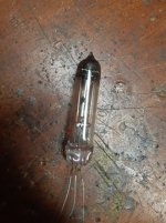
Can a ballast tube be used as a CCS in an amp, say rather than a SS CCS used on the plate rather than a choke or a resistor? Maybe as a Cathode bias? There seems to be a large list of available tubes, although finding one to meet an exact requirement would likely be difficult. What would be the result it using one if it can be used. These were kind of the LEDs of the day? I have never seen such a thing, but ......
If I remember correctly, a 25 Watt incandescent light bulb is very similar to a ballast.
It has a very unstable resistance, depending on how much voltage you put across it.
And that means an unstable current, as voltage is varied.
I think you will find that the ballast tubes typically have low to medium resistance, generally not good to use as a plate load.
A CCS has constant current . . . change the voltage across it, and the current stays very constant.
It is a very high impedance.
Do you want to put a ballast in your amplifier?
What part of the circuit would you put it in?
What good function would you expect it to do?
Last edited:
I was thinking about using a ballast instead of a plate resistor or choke, from what I have been reading once the voltage drop is set and at a certain current, based on selection of the ballast, the ballast naturally regulates current fluctuations better than a choke, they were used to regulate power. At this point I have no real plan, just a curiosity at how well this would work in practice. There is literally hundreds of these tubes built for any static voltage, current regulation. How many of these can still be found is another issue.
sser2,
Thanks for that accurate answer.
That reminds me of the Wien Bridge Oscillator that used a small incandescent lamp
to keep the output amplitude constant.
In later implementations of that circuit, a rectifier, integrating RC and JFET was used to keep the amplitude constant.
What made the small incandescent lamp work was the long thermal time constant that was very much longer than an alternation of 20Hz (the lowest frequency of the oscillator).
sser2,
Thanks for that accurate answer.
That reminds me of the Wien Bridge Oscillator that used a small incandescent lamp
to keep the output amplitude constant.
In later implementations of that circuit, a rectifier, integrating RC and JFET was used to keep the amplitude constant.
What made the small incandescent lamp work was the long thermal time constant that was very much longer than an alternation of 20Hz (the lowest frequency of the oscillator).
Using the small incandescent lamp in the FB of an oscillator was an invention of Bill Hewlett of HP during his post grad days, late 1930s. HP oscillators based on that cct sold very well, they were a big improvement on what was used before. One of the first users was Walt Disney Studios during the production of the movie 'Fantasia'. Think they bought six of the early version, HP 200A.
")
If I remember correctly, a 25 Watt incandescent light bulb is very similar to a ballast.
It has a very unstable resistance, depending on how much voltage you put across it.
And that means an unstable current, as voltage is varied.
I think you will find that the ballast tubes typically have low to medium resistance, generally not good to use as a plate load.
A CCS has constant current . . . change the voltage across it, and the current stays very constant.
It is a very high impedance.
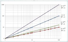
Many incandescent bulbs have a voltage vs current relation that forms a curve that is approximately the inverse of the so called 3/2s curve of a vacuum diode. On a log-log graph the slope varies from about 0.6 to 0.8 whereas an ordinary resistor has a slope of One. On a log - log graph a vacuum diode has a slop of 3/2s.
A carbon filament bulb has a slope of One on a log-log scale.
Do you want to put a ballast in your amplifier?
What part of the circuit would you put it in?
What good function would you expect it to do?
I was thinking about using a ballast instead of a plate resistor or choke, from what I have been reading once the voltage drop is set and at a certain current, based on selection of the ballast, the ballast naturally regulates current fluctuations better than a choke, they were used to regulate power. At this point I have no real plan, just a curiosity at how well this would work in practice. There is literally hundreds of these tubes built for any static voltage, current regulation. How many of these can still be found is another issue.
The incremental resistance of many incandescent bulbs at the normal operating temperature is roughly 10X the cold resistance. Another example is a vacuum tube heater, the heater of the 6L6 at operating temperature has an incremental resistance 9X its cold resistance.
None of these are anything like an LED or other semiconductor diode. The voltage vs current is the other way around.
Using the small incandescent lamp in the FB of an oscillator was an invention of Bill Hewlett of HP...
He got it, probably through Terman, from Mecham.
Wien bridge oscillator - Wikipedia
https://worldradiohistory.com/Archive-Bell-System-Technical-Journal/30s/Bell-1938d.o.pdf -- page 86 of 34MB PDF file.
Mecham worked at RF while H-P did audio; the gain-control hardly knows the difference.
Yeah that "light bulb" in the Wien Bridge is a Self Heating Thermistor.
Useful in some applications, still.
I have a few DAQ boards that use a small "oven" to stabilise the voltage ref for the ADC
On further inspection, one oscillator has a simple 9mm MES bulb, and the other Thermistor.
I wonder if the Thermistor was a 'modification'?
On further inspection, one oscillator has a simple 9mm MES bulb, and the other Thermistor.
I wonder if the Thermistor was a 'modification'?
The thermistor resistance reduces as temp goes up. The tungsten light bulb goes the other way. Carbon filament lamp resistance stays essentially constant with temperature.
Some Power Series Plots
The top line is an ideal vacuum diode following the 3/2s Law.
Next down is a perfect resistor where Slope = 1.
Next down is some incandescent light bulbs. Slope from 0.6 to 0.8.
Bottom is a square root.
Scales are in arbitrary units. All log-log.
The top line is an ideal vacuum diode following the 3/2s Law.
Next down is a perfect resistor where Slope = 1.
Next down is some incandescent light bulbs. Slope from 0.6 to 0.8.
Bottom is a square root.
Scales are in arbitrary units. All log-log.
Attachments
N101N,
Distortion is intrinsic.
Imagine a Trombone that only puts out a pure sine wave.
Imagine a Guitar string that only puts out a pure sine wave.
Imagine a really cheap function generator that puts out a pure sine wave.
Imagine a loudspeaker that only puts out a pure sine wave.
Imagine . . .
Distortion is intrinsic.
Imagine a Trombone that only puts out a pure sine wave.
Imagine a Guitar string that only puts out a pure sine wave.
Imagine a really cheap function generator that puts out a pure sine wave.
Imagine a loudspeaker that only puts out a pure sine wave.
Imagine . . .
There are many ways to create a distortion generator.
Might make an interesting guitar amp then.
Interesting, I looked up Gyrator chokes, it looks like they could work well in a power supply but not so good as a plate choke, unless your intent is to add some distortion. Any idea what this distortion would sound like? Since it would be limited to the voltage applied I assume it would not be at all like a swing choke, in fact it would be more like a saturated choke? More of a current limiter? I don't see how it could store energy like a choke.
I have built and listened to 2 stage self inverting push pull low power amplifiers.
They will not meet the requirements of many on this forum.
Some have already Poo Poo'd them.
A Triode Driver drives one output tube control grid.
The second output tube control grid is grounded.
The output tube cathodes are tied together, and returned to ground through a current sink.
Current Sink 1: A Bipolar transistor with emitter sense resistor, and base that is biased to set the total quiescent class A current.
No stored energy in the current sink.
Current Sink 2: A Choke in series with a resistor (total of DCR and resistance sets the quiescent class A current).
There is stored energy in the current sink. Pick a good choke, that works well down to 20Hz, does not saturate, and that has low distributed capacitance across the coil, and low capacitance to ground (choke frame).
The driver is single phase.
The output has 2 Local feedback loops:
Cathode to Cathode
Plate to Plate
No other negative feedback.
Use push pull output transformers that have low leakage inductance from one 1/2 primary to the other 1/2 primary.
The driver provides some 2nd harmonic distortion.
The output stage is push pull. As such, it provides relatively symmetrical output impedance to the loudspeaker.
That helps to reduce woofer "non-symmetrical cone walking"
The output also deals with the elliptical load of the loudspeaker fairly well.
Most of those self inverting amplifiers got converted to use a solid stage current sink and cathode coupled dual triode input/splitter/driver stage.
The output tubes of the converted amps are now individually self biased.
But I still listen to the 6BX7 self inverting push pull amp with choke and resistor current sink.
Simple.
"You should make things as simple as possible, but no simpler" Albert Einstein.
Most of you will never try this. that's OK.
Last edited:
- Status
- This old topic is closed. If you want to reopen this topic, contact a moderator using the "Report Post" button.
- Home
- Amplifiers
- Tubes / Valves
- Ballast Tubes as a CCS