Hello everyone, silly questions are coming for some
I have found many information about circlotronic circuits, all cathode coupled. Some with transformer and a lot more transformerless.
I was wondering, how can i reduce the output impedance of an OPT without the need of huge driving voltage swing? Why not an anode coupled circlotron?
I can see the need of several separated PSUs. What other drawbacks are there? There must be a reason i can't find such an approach, not even in a test bed as failure
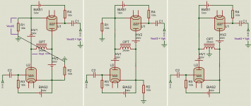
Below you can see what i mean

I have found many information about circlotronic circuits, all cathode coupled. Some with transformer and a lot more transformerless.
I was wondering, how can i reduce the output impedance of an OPT without the need of huge driving voltage swing? Why not an anode coupled circlotron?
I can see the need of several separated PSUs. What other drawbacks are there? There must be a reason i can't find such an approach, not even in a test bed as failure
Below you can see what i mean
Can be done.An interstage transformer with each power tube a winding between cathode and grid.And the hole power stage left floating.
But there is no difference with the output between cathodes, after all it's a series connection, tube-supply.
Without a coupling transformer you have to choose a reference point for the drive, try it.
Mona
But there is no difference with the output between cathodes, after all it's a series connection, tube-supply.
Without a coupling transformer you have to choose a reference point for the drive, try it.
Mona
Do you want series-applied voltage feedback to reduce your output impedance and distortion? If so, you will have to develop more drive voltage. That's how series-applied voltage feedback works.
Do you just want the advantage of the whole winding being used by both tubes simultaneously, instead of each tube having its own half-winding? Usually it is hard to find an appropriately-sized output transformer with the correct turns ratio for this application. Most transformers with the right turns ratio will be meant for parallel output tubes and be built for higher power levels than needed in a circlotron config. Do you have a transformer already in mind?
Do you just want the advantage of the whole winding being used by both tubes simultaneously, instead of each tube having its own half-winding? Usually it is hard to find an appropriately-sized output transformer with the correct turns ratio for this application. Most transformers with the right turns ratio will be meant for parallel output tubes and be built for higher power levels than needed in a circlotron config. Do you have a transformer already in mind?
People, spirakos has a Good idea.
Ketje, Good idea to use interstage transformers.
jhstewart9, Good point about the different impedances.
However, the load was labeled OPT (output transformer). True, the secondary was not shown.
A 2k transformer driven by 2 6AS7 plates (2 x rp; 280 x 2 = 560 Ohms).
2k/560 = 3.57 damping factor (only if the transformer is lossless).
A 300B with a 2500 Ohm OPT also has a damping factor of 3.57 (again, only if the transformer is lossless).
The advantage of the plates driving the OPT, is the gain is ~ 2 times greater than the cathodes driving the OPT.
That means the drivers only need 1/2 the drive voltage to drive the 6AS7 in plate output mode, versus using 6AS7 cathode followers output.
Last edited:
I guess I don't understand the goal. If the goal is to eliminate the large drive requirements of the conventional 50% feedback arrangement of the circlotron, why not just use a conventional output stage topology and transformer? Conventional circuits are easy to drive too.
What are the design goals and is this the best way to accomplish them?
What are the design goals and is this the best way to accomplish them?
With perfect output tube quiescent current balance, the output transformer can have interleaved laminations (no air gap). Interstage transformers make the circuit quite easy to implement.
And a single driver can drive 2 interstage transformers, so no phase splitter is necessary.
But then the same can be said for a traditional push pull 6AS7 output stage, that has perfect quiescent current balance. No air gap required in the output transformer.
But this circuit does require a phase splitter circuit, unless you use a phase splitting interstage transformer (or phase splitting choke).
The Circlotron arrangement does not need an OPT with gap in the magnetic cct. There is no DC in the OPT primary. The version of the Circlotron with an OPT I built 20 yrs ago using PP KT88s or 6550s managed an easy 50+ watts with low distortion. All appeared in an article in AudioXpress magazine.
The plate drive arrangement creates more problems than it solves.")
The plate drive arrangement creates more problems than it solves.
1. The circuit in post # 1 has to have pretty identical B+ supplies and pretty identical KT88s;
Or else the bias of the 2 KT88s has to be carefully set so that there is no DC load current.
Otherwise, there will be DC current in the load.
And if the bias supplies are not regulated, and/or if the B+ supplies are not regulated, sooner of later, there will be DC current in the load.
For that matter, if the KT88 filament supplies are not regulated, sooner or later there will be DC current in the load.
Matching occurs at one quiescent state.
A change of any part of that state, and "Your Mileage May Vary.
2. I do not have a copy of the AudioExpress with your Circlotron, but I can guess:
As your Circlotron was designed, that does make for some stability.
Using larger B+ voltages, cathode self bias, and other techniques will make it easier to reduce or eliminate the DC load current, even with unregulated B+,
unregulated filament supplies, and the effects of tube aging.
I expect that is an advantage of your Circlotron, using the cathodes to drive the output transformers.
The disadvantage is the larger drive voltage required for a given output tube.
Last edited:
Hello all and thanks for your contribution
This is not a project that have to be accomplished. If we conclude that there is no unapproachable problem then i will give it try
An IST seems the best solution but i would prefer not another iron. Thar will be examined later
Making my own OPT is also a goal! Working on it..
Maybe the design goal is not worth, this is what we discuss here
About current balance i guess some type of servo bias is unavoidable for class AB
PSU complexity is not a problem, neither the OPT
The issues need a solution so far is the current balance at all circumstances and how to make a reference point for both driving stages and bias
This is not a project that have to be accomplished. If we conclude that there is no unapproachable problem then i will give it try
Can be done.An interstage transformer with each power tube a winding between cathode and grid.And the hole power stage left floating.
But there is no difference with the output between cathodes, after all it's a series connection, tube-supply.
Without a coupling transformer you have to choose a reference point for the drive, try it.
Mona
An IST seems the best solution but i would prefer not another iron. Thar will be examined later
Do you just want the advantage of the whole winding being used by both tubes simultaneously, instead of each tube having its own half-winding? Usually it is hard to find an appropriately-sized output transformer with the correct turns ratio for this application. Most transformers with the right turns ratio will be meant for parallel output tubes and be built for higher power levels than needed in a circlotron config. Do you have a transformer already in mind?
Making my own OPT is also a goal! Working on it..
Not an OTL. The 2K OTP is a transformer. Secondary omitted for simplicitySource impedance looking back into the plates is higher than looking back into cathodes. Low DF is already a problem with OTLs, the proposed cct makes it worse.
This is the main idea. Half voltage drive than cathode coupled and half impedance than conventional PP. I think that this topology fits better with pentodes that have higher μ and will need much less driving voltage but i already have some 6AS7..The advantage of the plates driving the OPT, is the gain is ~ 2 times greater than the cathodes driving the OPT.
That means the drivers only need 1/2 the drive voltage to drive the 6AS7 in plate output mode, versus using 6AS7 cathode followers output.
I guess I don't understand the goal. If the goal is to eliminate the large drive requirements of the conventional 50% feedback arrangement of the circlotron, why not just use a conventional output stage topology and transformer? Conventional circuits are easy to drive too.
What are the design goals and is this the best way to accomplish them?
Maybe the design goal is not worth, this is what we discuss here
About current balance i guess some type of servo bias is unavoidable for class AB
PSU complexity is not a problem, neither the OPT
The issues need a solution so far is the current balance at all circumstances and how to make a reference point for both driving stages and bias
Last edited:

I think it's pretty cool that you are considering making a circlotron with your own transformer.
I would recommend the conventional 50% feedback configuration with the transformer tied to cathodes. You just have to develop large voltage swings to drive it, which is doable, and it will be very low distortion and Zout.
If you aren't averse to mosfets in your design, I developed an approach with CCS-loaded pentodes that has practically no distortion compared to every other approach I have ever seen. See here: Idea for driver for CF output stage
There is some discussion on schematics and simulation in Multism here
Attached is the cleanup version of original for study purpose. Of course you can study the original patent for details advantages.
Attached is the cleanup version of original for study purpose. Of course you can study the original patent for details advantages.
Attachments
That's no circlotron.It's a PP with cathode feedback.There is some discussion on schematics and simulation in Multism here
Attached is the cleanup version of original for study purpose. Of course you can study the original patent for details advantages.
Mona
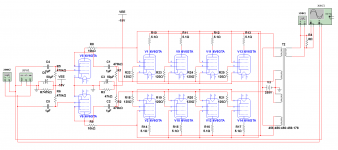
Thermal runaway of the 6V6s is a sure thing, fixed bias & four of 6V6 on each side sharing a single 470K grid resistor. Watch for smoke!There is some discussion on schematics and simulation in Multism here
Attached is the cleanup version of original for study purpose. Of course you can study the original patent for details advantages.
Sorry here it's. The previous is also there for purpose of comparison of output impedance.That's no circlotron.It's a PP with cathode feedback.
Mona
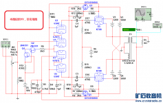
The poster also said (translation), I think he meant "decrease the distortion":
"Over the past few years, I have also bought a Circlotron amplifier using KT88, which has also been uploaded here.
In order to obtain a good phase inversion effect, I used two 2N4391 cascaded constant current sources; in order to ensure that the driving stage has a sufficiently large voltage output amplitude, two IXTU01N100 are used to form a simulated inductor with a very large equivalent inductance (Not a constant current source). These two analog inductors can also significantly increase the distortion caused by "isolating" the bootstrap circuit."
Attachments
Last edited:
Thermal runaway of the 6V6s is a sure thing, fixed bias & four of 6V6 on each side sharing a single 470K grid resistor. Watch for smoke!
Here is the other poster explanation:
"..if you use an ideal transformer, and the impedance ratio of the output transformers of the two circuits is the same (Mcintosh circuit is a single-arm primary and secondary ratio), then the output impedance of the two is completely the same.
In addition, I think that compared with the standard series push-pull circuit, the output impedance of the Circlotron circuit will not necessarily be a fraction of the standard series push-pull circuit, but is closely related to the characteristics of the output tube used. When the trans conductance of the output tube is higher, the negative feedback of the output stage of the Circlotron circuit or the Mcintosh circuit is also deeper, and the output impedance is lower.
A problem was found, whether it is 6P1 or 6V6, the first gate resistance is not greater than 500K when self-biased, and the number of 6P1 should not be found when the bias is fixed. It is estimated that the actual application is almost not more than 100K as 6V6. If you use four tubes in parallel, then the value of R1 and R2 should not be greater than 25K, 470K is obviously inappropriate. However, the load impedance of 25K as the driving stage is too low, and this problem needs to be solved."
Last edited:
A problem was found, whether it is 6P1 or 6V6, the first gate resistance is not greater than 500K when self-biased, and the number of 6P1 should not be found when the bias is fixed. It is estimated that the actual application is almost not more than 100K as 6V6. If you use four tubes in parallel, then the value of R1 and R2 should not be greater than 25K, 470K is obviously inappropriate. However, the load impedance of 25K as the driving stage is too low, and this problem needs to be solved." Last edited by Koonw; Today at 10:22 AM.
Drive the parallel group with a CF, grid current problem solved.
Use the CF to provide bias at low impedance.
Drive the parallel group with a CF, grid current problem solved.
Use the CF to provide bias at low impedance.
- Status
- This old topic is closed. If you want to reopen this topic, contact a moderator using the "Report Post" button.
- Home
- Amplifiers
- Tubes / Valves
- Anode coupled circlotron with transformer