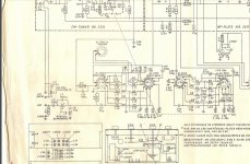
In that case they must be early diode rectifiers not selenium what shape and material is it made out of ?
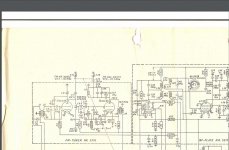
The combined capacitor is bad news I had to replace every one due to leakage between them.
The tubes are standard British type B9A based I have them all in my spares box usually quite reliable
The combined capacitor is bad news I had to replace every one due to leakage between them.
The tubes are standard British type B9A based I have them all in my spares box usually quite reliable
Last edited:
B250 C75 is a bridge selenium rectifierIn that case they must be early diode rectifiers not selenium
Thanks TG---If it is it is recommended that a surge protection resistor be fitted --not my words but the original manufacturers of selenium rectifiers backed up by electronic hardware engineers of the time.
If you check up that type needs a current limiter as without it its normal working life is shortened and/or efficiency is affected .
That would then mean you should not go much above the recommended reservoir / smoothing capacitor value.
I couldn't find that rectifier in my equivalents book.
If you check up that type needs a current limiter as without it its normal working life is shortened and/or efficiency is affected .
That would then mean you should not go much above the recommended reservoir / smoothing capacitor value.
I couldn't find that rectifier in my equivalents book.
C274AC25160AA0J PP metallisert filmkondensator for motordrift 16uF +-5 % KEMET
its not that expensive for a 16 uf film capacitor
its not that expensive for a 16 uf film capacitor
Yes under £4 sterling I don't speak Norwegian but the words have some German origin in them and I know a few German words as I watch German TV on satellite .
Those capacitors are cheap because they are meant for Electric motors so they are made out of very cheap packing grade polypropylene might be okay for a tube radio but NOT okay for anything hi-fi.
Those capacitors are cheap because they are meant for Electric motors so they are made out of very cheap packing grade polypropylene might be okay for a tube radio but NOT okay for anything hi-fi.
Is this hifi?
C4AQSBW5170A3MJ Kondensator, radial 17 uF +-5% KEMET | Elfa
From What i have heard i thought kemet made good capacitors.
C4AQSBW5170A3MJ Kondensator, radial 17 uF +-5% KEMET | Elfa
From What i have heard i thought kemet made good capacitors.
Thats better Fjellreven , notice its a smaller capacitance but dearer does that not tell you something ?
N101N it aint "hard to be sure " electric motor capacitors were never designed for hi-fi .
Maplin electronics --now dissolved sold them - cheap as chips I bought several in the ,80,s opened one up cheap internals .
Look JLH in a long article in EW around the early ,80,s on passive components said the same .
Sadly John is no longer with us but D.Self is --ask HIM if he would fit and use those motor capacitors in his cutting edge designs .
They generate distortion, can leak due to their thinness , tell me what pukka audio design engineer has fitted them to their designs ?
I havent come across any it would be embarrassing to do so unless it was just a test to -see if it works .
Dig out your $100000 spectrum analyzer run a minus 100db or more pure RMS 20Khz test signal through one of those capacitors and into the spectrum analyzer take a long hard look at the peaks and you wont question me again about it.
- Status
- This old topic is closed. If you want to reopen this topic, contact a moderator using the "Report Post" button.
- Home
- Amplifiers
- Tubes / Valves
- Ordering from Justradios.com