
... those Silver mica capacitors are made by Indian ruby muscovite a manufacturer that i know nothing about.....
Muscovite is the ROCK that mica comes from. A lot of it comes from India. There's different colors, I bet "ruby" is a red/pink mica.
This says NOTHING about who made it or what quality it is.
Good modern commercial caps of appropriate voltage rating are "high quality" and should be reliable; plastic/film caps should last the rest of your life. Put in a good cap and enjoy the music.
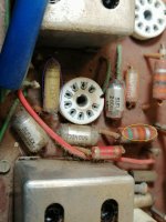
i have put a colored circle on every component i want to know the name of them and if they need to be replaced. there`s also a number on every picture.anyway on
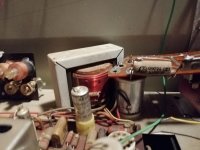
the fourth picture there`s a big capacitor holding the rectifier board in place can i replace it with a dc motor where i have taken out the all the components and then put rubber on the motor so it fits and then solder it to the rectifier board.i am aware that a broken dc motor cant be used as a capacitor but i think it should work good enough to hold the rectifier board in place.and yes you are right i am from Scandinavia i was born in Norway and my username means mountain fox.yeah and also thanks for all the help this is the first tube radio i have attempted to recap.and don`t worry i am not doing wholesale recapping.and also you have to open the pictures to see the circles.
the fourth picture there`s a big capacitor holding the rectifier board in place can i replace it with a dc motor where i have taken out the all the components and then put rubber on the motor so it fits and then solder it to the rectifier board.i am aware that a broken dc motor cant be used as a capacitor but i think it should work good enough to hold the rectifier board in place.and yes you are right i am from Scandinavia i was born in Norway and my username means mountain fox.yeah and also thanks for all the help this is the first tube radio i have attempted to recap.and don`t worry i am not doing wholesale recapping.and also you have to open the pictures to see the circles.
Attachments
Get you -
No 3- old school ceramic capacitor
No 1- 60,s film capacitor
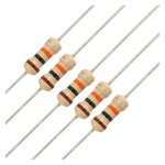
No 4- power resistor
No 2- RED=polystyrene capacitor---Orange looks like another polystyrene capacitor OR film capacitor --- Yellow- 61K -1 watt 10% resistor
No colored circle on picture 4 so guess you are talking about the resistor top right.
No 3- old school ceramic capacitor
No 1- 60,s film capacitor
No 4- power resistor
No 2- RED=polystyrene capacitor---Orange looks like another polystyrene capacitor OR film capacitor --- Yellow- 61K -1 watt 10% resistor
No colored circle on picture 4 so guess you are talking about the resistor top right.
No already knew it was a Power resistor, what i wanted to know on the fourth picture is whether or not i can use a modified dc motor with some rubber attached to it to hold the rectifier in Place. i can't find a 32/33uf 350v capacitor that is so big it can hold the rectifier board. And what i meant with modified is that the motor parts are removed Basically making it a tin can with two isolated leads.
That 1 watt resistor was normal in the 60,s ,its carbon and 1 watt metal film were not used then which are much smaller.
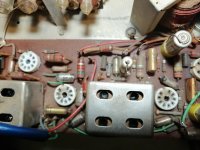
32/32uf in one can were standard for a power supply in those days for a tube rectifier , one acts as the reservoir and the other smoothing for the HT+ (plate ) .
What you want is a tube (valve ) holder used in portable tube equipment . The tube base had a metal ring round it and a steel wire clip to hold the tubes in place.-
COMPONENTS - VALVE BASES & TOP CAPS – Page 2 – MULLARD MAGIC
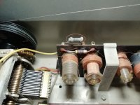
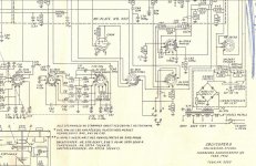
If that transformer is a mains transformer then the output went to the rectifier .
If its an output transformer then you have a direct mains feed to the rectifier see-
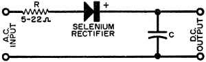
Using Selenium Rectifiers, October 1947 QST - RF Cafe
Of course the old rectifier can be replaced with modern diodes ---BUT-- you will have to fit series high wattage limiting resistors as the new diodes will give a higher output than the selenium rectifier.
If its an output transformer then you have a direct mains feed to the rectifier see-
Using Selenium Rectifiers, October 1947 QST - RF Cafe
Of course the old rectifier can be replaced with modern diodes ---BUT-- you will have to fit series high wattage limiting resistors as the new diodes will give a higher output than the selenium rectifier.
As with tube rectifiers that's down to WHAT selenium rectifier is fitted .
In that type of rectifier --a "radio type " no vanes a surge limiting resistor MUST be included - eg- 5ohms--7ohms .
This is fitted BEFORE the rectifier NOT after and the total capacitance --AFTER the rectifier unlike a tube rectifier.
Do NOT neglect to fit the surge resistor without it you can blow the rectifier .
In that type of rectifier --a "radio type " no vanes a surge limiting resistor MUST be included - eg- 5ohms--7ohms .
This is fitted BEFORE the rectifier NOT after and the total capacitance --AFTER the rectifier unlike a tube rectifier.
An externally hosted image should be here but it was not working when we last tested it.
Do NOT neglect to fit the surge resistor without it you can blow the rectifier .
- Status
- This old topic is closed. If you want to reopen this topic, contact a moderator using the "Report Post" button.
- Home
- Amplifiers
- Tubes / Valves
- Ordering from Justradios.com