The schematic in post # 1 solves the grid return resistance problem nicely.
I understand your post and can apply your calculations myself, thank you.
But I would appreciate an off-hand comment about the following.
I have a 12x6L6GC power section with fixed bias (I didn't design it).
Each 6L6 has a 47K grid stopper and 270K grid leak (the spec is 100K max).
Each side is driven by a single 12au7 cathode follower in the usual way.
I would guess that this design depends upon that 12au7 *not* being able to drive into AB2 (or not far enough to blow it up). Do you think so?
***
To original poster: Yeah, it looks beautiful and I'll be thinking about it.
")
Last edited:
Is the AU7 directly coupled to the 6L6 grids? If so, that may not be a problem, other than not being able to individually bias. It’s output impedance would be low enough that the effective grid leak would be dominated by the stopper. If it is capacitively coupled, they are taking the usual liberties with grid leak, which doesn’t always end well. And if it is capacitively coupled you cannot drive into AB2. You could always use a beefier K-follower and use a 100k Or even 47k grid leak on each output tube. If it is capacitively coupled, you could go down to 1k for the stopper. Both halves of a BH7 in parallel could drive that, as could an EL84 or 6V6/ 6W6, if you can stand the heater current.
If it is capacitively coupled, they are taking the usual liberties with grid leak, which doesn’t always end well.
It's capacitively coupled. I understand your post. Thank you very much.
LetItGrowTone,
I am not sure exactly what the circuit is that you described.
But from what I think I understand, I would only use that amplifier
right next door to the fire station.
And I am not sure that a single 12AU7 cathode follower can drive all of that at low distortion, not even with the outputs in Class A.
I believe the cathode impedance is about 450 Ohms.
Especially if the 6L6 tubes are either in Triode Wired Mode, or in Ultra Linear Mode.
You have to drive the resistive load, which is in parallel with the Miller Effect Capacitance too.
Schematic . . . please post it.
I am tired of being blindfolded, turned around an unknown number of degrees, and then asked to use a bow and arrow to hit the target.
Last edited:
I admire the circuit and the handiwork of the original poster and didn't intend to derail the thread, but the exact topic came up so I asked my question "in passing", not intending to put anyone to work.
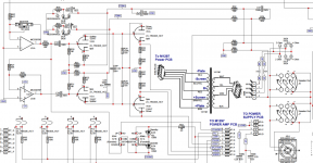
The schematic for anyone really wanting to wade through it is on the Internet here: https://traynoramps.com/framework/uploads/2020/01/Manual-Service-YBA100-YBA300-00-2v0A.pdf
The poweramp schematic is about 50% down the page labeled "YBA300 Output" and the preamp/driver is about 80% down "YBA300 PRE-AMP".
You'll see that the gist of the matter is as I said.
***
The original poster's circuit looks like it was inspired by the SVT, and the discussion has helped me understand the SVT better, thanks again.
Why do I always get sucked into these Guitar Amplifier questions on the Tubes / Valves part of this Forum.
!@#$%^&*
I purposely do not go to the Instruments & Amps part of the Forum.
Please tell us up front that the question regards some guitar amplifier.
Even if you name the product make and model, I/we may not recognize the fact that it is a Guitar amplifier, considering the thousands of Guitar Amplifiers.
Yes I/we do recognize a few names, Fender, Mesa Boogie, etc.
I am thanking all of you in advance for mentioning up front, that this regards a Guitar amp.
Thanks from lots of us Hi Fi types that go to this Tubes / Valves part of this Forum.
Also, I am not a Software lover. The schematics on that post are unreadable to me. I can not expand them, and then have to readjust my computer to do all the other work I do with it.
Last edited:
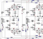
These are snips from the above linked document which is posted on the Internet by Traynor. These snips are for the convenience of anyone interested in the specific topic we were discussing.
Power amp:
+PLATE, -PLATE go to transformer
SCREEN+, SCREEN- to to transformer
+GRID, -GRID come from the driver in the other schematic
Try to ignore the error detection and automatic disconnect circuitry for each pair.
Preamp:
12AU7 driver is in the middle. Its outputs here are labeled PGRID, NGRID as they enter the connector at the lower right, and become +GRID -GRID on the other schematic.
***
There's a lot I admire in the circuit, and some I would remove or adjust someday, just as I always do. Don't intend to criticize Traynor at all.
Attachments
I asked for just an "off hand comment" because I didn't intend to distract from the thread, and I didn't intend to put anyone to work.
My question was within the flow of the discussion in this thread and was not guitar or hifi specific. Name of manufacturer was irrelevant and I didn't want to criticize them.
Somebody asked for the schematic, so I supplied it.
Apologize for annoying anyone. Thanks to everyone.
My question was within the flow of the discussion in this thread and was not guitar or hifi specific. Name of manufacturer was irrelevant and I didn't want to criticize them.
Somebody asked for the schematic, so I supplied it.
Apologize for annoying anyone. Thanks to everyone.
Ok, now I can see the circuit.
Thanks!
1. Output tube Pin 1, Suppressor Grid is connected to Pin 8, Cathode.
It has to be either an EL34 or other similar tube, not a 6L6GC, which has the Beam Formers internally connected.
The 6L6GC will not be hurt by the extra connection, But . . .
(When in Fixed Bias mode, a 6L6GC has a much tighter max g1 grid resistance than an EL34 does).
For fixed bias, the 6L6GC spec is </= 100k, EL34 spec is </= 500k.
The circuit has 317k. Smoking 6L6GC tubes (your mileage may vary).
2. Using a single bias pot for two output tubes, is like trying to match the dual carburetors on the Datsun 240Z engine.
One of my co-workers got rid of his 240Z because of that.
"Man with one watch knows the time, man with two watches is never sure." - source is unknown to me.
3. The outputs appear to be in Ultra Linear Mode. That means there may be significant
Miller Effect capacitance for the single 12AU7 cathode to drive 6 grids without phase shift.
Probably quite different g1 to g2 capacitances of the 6L6GC versus the EL34 (so Miller effect capacitive reactance would be different too).
Negative feedback adjustments anybody?
Last edited:
I sincerely regret annoying you, 6A3sUMMER.
1) It is intended by the manufacturer to take 6L6GC or EL34 (but came with 6L6GCs). Since the EL34 can take the greater grid circuit resistance I'll just switch to EL34. (My favorite amp is 2xEL34 trioded, so this one could end up that way someday.)
2) Good analogy. I agree.
Thank you again.
I look forward to any more discussion about the amp in the original post.
Last edited:
LetItGrowTone,
It's OK. I am often very bad.
On a similar note, I inherited a couple of non working Parallel Push Pull EL34 Amplifiers.
Heavy as a Boat Anchor.
The good thing about the amp is the circuit uses individual self bias pots (4, one for each EL34).
The driver has rather high output impedance, so the g1 grid resistance was chosen to be near the 500k EL34 limit.
And the outputs are Ultra linear, causing the larger g1 Miller Effect capacitance.
Unfortunately, someone put 6550 tubes in the amplifier.
In self bias, the 6550 max g1 grid resistance specification is 50k Ohms.
Of course, the amps blew up.
I just hope that becomes a lesson to those who wish to cheat the tube specifications.
You might want to add some ballast resistors across the 1N5408 diodes in the power supply to make sure the two diodes in each branch share the reverse voltage evenly. Something in the 1-10 MΩ range is probably fine.
Are the two 430 V transformers effectively in parallel? The supply schematic shows two rectifier bridges, but only one is connected (per the schematic anyway).
Tom
Are the two 430 V transformers effectively in parallel? The supply schematic shows two rectifier bridges, but only one is connected (per the schematic anyway).
Tom
Well it was originally going to be a bass amp, but it sounded so good that it’s going to be hard not to build a nice tube SPL-oriented home audio system around it. The speakers have been in the planning stages for years, and I got the tube amp bug real bad this time. Most of my diy audio has been PA equipment, since I’ve had no real desire to upgrade my main music/TV system for the last 10 years. We plan to move to a big place in the country in 2 years or so (probably about when the pandemic lets up and we can start building). I’ll have room for a really loud rock and roll rig in the house.
The original design goals/constraints were: 200 watts, all tube amplification (no cheating), common tubes, and off-the-shelf iron. For the speakers I’m still looking for just the right 15’s. What I want is the exact tuning of the Kappa 15LF, but with a low distortion motor/suspension. I’m Very happy with the rest of the driver selection. There are a TON of18’s that fit the bill, but it makes the baffle too wide.
Any discussion of big amps and lessons learned are certainly welcome here. A tube subwoofer amp from Hell is on the horizon, and so is a 100-150 watt bass amp. That will likeLy get discussed in other threads when I get some actual hardware started.
You might want to add some ballast resistors across the 1N5408 diodes in the power supply to make sure the two diodes in each branch share the reverse voltage evenly. Something in the 1-10 MΩ range is probably fine.
Are the two 430 V transformers effectively in parallel? The supply schematic shows two rectifier bridges, but only one is connected (per the schematic anyway).
Tom
Yes, the two 430V trafos are in parallel. It is two complete power supplies paralleled. Good catch on the schematic error - they are both supposed to be connected. A single 400 VA trafo would probably work for music, but be overloaded with sine wave testing. And probably sag too much. They are only $57 each. The first rule of military spending: why build one when you can have two at twice the price? The only real downside is the power supply has four transformers. At $200 shipped - and that trumps everything. I challenge anyone to get a custom wind job on an 800-1000 VA trafo for that.
I(My favorite amp is 2xEL34 trioded, so this one could end up that way someday.)
That does actually sound really nice. Tried it once, but the output iron was less than optimal (R a-a too high to get any real power). It did make 10 really nice sounding watts. Some day I may get the appropriate iron and try again.
The coupling caps on the concertina could certainly go as high as 1uF. I’ve got a big batch of 1 uF 630V MKPs. The 0.1’s on the driver stage I’m sort of stuck with. They are located on a little vertical mount perfboard right between the front end and driver, with all the bias pots and associated components mounted on it. This kept all the leads short and fixed my original stability problem, as well as make it easy to a adjust bias from the topside. The first iteration had the bias board on the other side between the driver and output stages, with flying 1uF coupling caps mounted on the sockets. Worked fine at low levels. Get the driver stage up to about 20 volts, and it take off and go square wave, if the excitation was anything near 60 Hz. No idea why it was gain peaking at that frequency, so it all had to come down to parasitiics. This was before ever installing an output tube or even thinking about a feedback loop. This issue took weeks to resolve, and almost made me give up on the whole thing.
NFB can be a tricky think. Check the amp first with no NFB. Motor-boating can also be a real problem with two sets a coupling caps. There are also multiple ways to solve the problem too - not easy. With LF it won't be parasitics but can also be supply decoupling to the first stage. Sometimes an amp that is close to the edge can go into oscillation when the final stage enteres class B or another stage saturates. I had an amp which sounded just fine until you removed the speaker grill and could see the woofer moving in and out at 2Hz. That needed lead-lag compensation to fix. I think you need a sound understanding of feedback loops to get this part right there's no way of skipping the maths. Simulation can also be useful in this area if you can get a model of the OPT.
Last edited:
So I see you have made the coupling break frequency of both filters around 5Hz. I don't know you transformer break frequency but if its around 5Hz you will be in trouble. If you want the run with just lag compensation for LF, then one of the three poles should be dominate and the others should not kick in until the feedback gain is around unity. If transformer is no good you can make it the transformer - else it needs to be one of the other coupling stages.
So if you have a good transformer say 5Hz -3dB point then you can place one of the coupling stages to have a much higher break frequency say 20Hz. The feedback will compensate for this but the stage before must be able to drive say twice the voltage at LF. I would think you could increase the plate resistors from 18k on the pre-driver. The other coupling stage you would move to say 1-2Hz. The idea is that at 20Hz the feedback drops by 3dB. It must then continue to drop at -6dB/octave until you get to unity gain where the transformer pole kicks in. As you cross unity gain you need to have a reasonable phase margin.
Its not easy to explain - hope this sort of helps. What I cannot do is give you exact advise.
Last edited:
- Status
- This old topic is closed. If you want to reopen this topic, contact a moderator using the "Report Post" button.
- Home
- Amplifiers
- Tubes / Valves
- We've got a heartbeat - 6x 6550 is alive