My worries ...the bias point, with such low plate load.
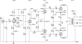
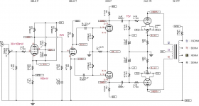
The 5k Plate to Plate primary is the first thing I noticed. Sorry I can’t offer specific help, but I agree that it merits further investigation. I have not seen a PP GM-70 schematic but I have seen several SE amp schematics and they usually specify plate loads of between 8k and 16k for SE. I have communicated with a transformer winder and he claimed that for an SE GM-70 to sound at its best a plate load of > 15k is needed. Where did you find the full schematic with PS?
The lack of a bypass cap on the 620 ohm cathode resistor on the first stage is also peculiar. Without it, one would tend to just tie the feedback resistor up above the 620 ohm resistor instead.
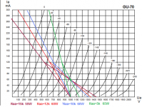
Hmm 5K with 1kV/60mA, grabage. You'll get about 15W class A from that amp. You could get more power with one GM70 in a single ended amp with a proper design.
Hmm 5K with 1kV/60mA, grabage. You'll get about 15W class A from that amp. You could get more power with one GM70 in a single ended amp with a proper design.
Attachments
The lack of a bypass cap on the 620 ohm cathode resistor on the first stage is also peculiar. Without it, one would tend to just tie the feedback resistor up above the 620 ohm resistor instead.
Hmm 5K with 1kV/60mA, grabage. You'll get about 15W class A from that amp. You could get more power with one GM70 in a single ended amp with a proper design.
Yes, that's correct.
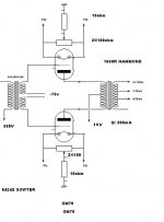
I have SE GM-70. Operating point 1200VDC 80mA with 7K transformer. Driver stage with IT transformer. Getting 30+ watts.
This product advertised as 100+100w??????The lack of a bypass cap on the 620 ohm cathode resistor on the first stage is also peculiar. Without it, one would tend to just tie the feedback resistor up above the 620 ohm resistor instead.
Hmm 5K with 1kV/60mA, grabage. You'll get about 15W class A from that amp. You could get more power with one GM70 in a single ended amp with a proper design.

According to my calculations, can reach 80w with 19% thd
probably snake oil.
That's much to optimistic, you get even less then 5W out in class A. Continuing class B there is over 60W with the Raa=5k.The lack of a bypass cap on the 620 ohm cathode resistor on the first stage is also peculiar. Without it, one would tend to just tie the feedback resistor up above the 620 ohm resistor instead.
Hmm 5K with 1kV/60mA, grabage. You'll get about 15W class A from that amp. You could get more power with one GM70 in a single ended amp with a proper design.
I would rather use Raa=12k, also 60W out too but more lineair.
There is a 330k from the cathode to +B4 allowing a smaller cathode resistor=more gain.The 620Ω would be 1k5 (without the 330k) reducing the gain by more then 2x.
The feedback is with ~10dB very reasonable.
I don't now why they made the amp so sensible, 10x less would be more then enough today.
Mona
Attachments
- Status
- This old topic is closed. If you want to reopen this topic, contact a moderator using the "Report Post" button.
- Home
- Amplifiers
- Tubes / Valves
- gm70 schematic question