Hello,
want to build a Cathodyne tube line pre.
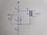
Could this schemo be a good starting point for the design?
Is a single ended 15K:600 Ohm output trannie of any use for this circuit?
Or will the output resistance of the circuit be too high and a different tranie must be used?
Many thanks for checking the schemo.
want to build a Cathodyne tube line pre.
Could this schemo be a good starting point for the design?
Is a single ended 15K:600 Ohm output trannie of any use for this circuit?
Or will the output resistance of the circuit be too high and a different tranie must be used?
Many thanks for checking the schemo.
Attachments
Schmitz77,
It is possible to make that circuit work.
That is a nice idea, but . . .
rongon,
But it is not a real parafeed amp.
Only if you put a bypass capacitor across Rc will it become a parafeed amp.
And by the way, it will perform better as a parafeed that way, than it will perform
as the Cathodyne circuit that was first drawn.
Schmitz77,
But why would you build it as a cathodyne?
Only to show it could be done.
1. The driving impedance to the transformer limits what transformer you have to use,
and even a really good transformer will have frequency response problems, rolling off at low frequencies, and rolling off at high frequencies.
You can use a Power tube, relatively low values for Rp and Rc, and stand lots of current, that will make for a lower impedance to drive the transformer, but what a power waste, and hot too.
2. The gain to the primary is limited (to 2x?, my brain hurts to much now to think about how to calculate that).
And the voltage loss in the transformer is 5:1 (0.2). 2 X 0.2 = 0.4 total gain, not a real line amp.
3. The output impedance of the line amp will very high, unless the primary to secondary turns ratio is high. That will reduce the gain, and further reduce the bandwidth. Or back to the power tube solution.
4. In a Cathodyne, Ra and Rc are equal. That means the grid has to be at a rather large positive voltage, just like all other cathodyne amps.
5. With a lower Rc resistance, and a bypass cap across Rc, the plate resistance goes down, and this becomes a practical parafeed amp (like the output transformer does not need as many laminations, does not need an air gap, and can have reasonable bandwidth). The tube gain goes up, and could overcome the 0.2 x voltage reduction of the output transformer, providing gain lots higher than unity.
That is just about all the reasons I can think of why it should not be built as a cathodyne.
Last edited:
Hello, want to build a Cathodyne tube line pre.
Are you looking for a balanced output, a floating output, or what?
Schmitz77,
Did you ever make it to the Deutsches Museum in Munich?
It was wonderful. And nicely placed between the natural river, and the
man-made river path.
Lots and lots of different and interesting stuff, including some behind-plastic large glass vacuum tubes with current meters, etc. that showed some tube fundamentals.
I visited it two times.
Some reading material about the cathodyne as a transformer driver (scroll down):
Octal Aikido All-in-One & Split-Load Phase Splitter Zo
Octal Aikido All-in-One & Split-Load Phase Splitter Zo
Last edited:
Schmitz77,
Did you ever make it to the Deutsches Museum in Munich?
It was wonderful. And nicely placed between the natural river, and the
man-made river path.
Lots and lots of different and interesting stuff, including some behind-plastic large glass vacuum tubes with current meters, etc. that showed some tube fundamentals.
I visited it two times.
An excellent idea. And a very good reason to visit Munich again.
Thank you!
Are you looking for a balanced output, a floating output, or what?
Just looking for a superior sounding parafeed 600 Ohm output stage beside an ordinary cathode follower.
Ken Shindo seems to do the output stage of his preamps this way, so I'm interested to do it the same way. Any cathode follower has its pros and cons, but in general it's not known to be the best of all audio circuits. I want to do something different, something better in the circuit.
"The C3m is also capable of very high gain, but Ken Shindo puts it to a different sort of use: In the Vosne-Romanee, the Siemens tube functions as a resistance-coupled phase inverter, the output of which appears across the anode and the cathode.
The now-balanced signals for the left and right channels are directed to that pair of vintage output transformers, with DC blocking along the way by those large, lovely, and similarly ancient Sprague oil caps.
That said, it seems possible to get a true balanced output from this preamplifier's XLR output jacks."
This looks like he is doing a simple split load Cathodyne output stage the same way as my schemo shows. With one 4uF oil coupling cap and an inverted and a non inverted signal feeding the output trannie.
Last edited:
Schmitz77,
It is possible to make that circuit work.
That is a nice idea, but . . .
rongon,
But it is not a real parafeed amp.
Only if you put a bypass capacitor across Rc will it become a parafeed amp.
And by the way, it will perform better as a parafeed that way, than it will perform
as the Cathodyne circuit that was first drawn.
Schmitz77,
But why would you build it as a cathodyne?
Only to show it could be done.
1. The driving impedance to the transformer limits what transformer you have to use,
and even a really good transformer will have frequency response problems, rolling off at low frequencies, and rolling off at high frequencies.
You can use a Power tube, relatively low values for Rp and Rc, and stand lots of current, that will make for a lower impedance to drive the transformer, but what a power waste, and hot too.
2. The gain to the primary is limited (to 2x?, my brain hurts to much now to think about how to calculate that).
And the voltage loss in the transformer is 5:1 (0.2). 2 X 0.2 = 0.4 total gain, not a real line amp.
3. The output impedance of the line amp will very high, unless the primary to secondary turns ratio is high. That will reduce the gain, and further reduce the bandwidth. Or back to the power tube solution.
4. In a Cathodyne, Ra and Rc are equal. That means the grid has to be at a rather large positive voltage, just like all other cathodyne amps.
5. With a lower Rc resistance, and a bypass cap across Rc, the plate resistance goes down, and this becomes a practical parafeed amp (like the output transformer does not need as many laminations, does not need an air gap, and can have reasonable bandwidth). The tube gain goes up, and could overcome the 0.2 x voltage reduction of the output transformer, providing gain lots higher than unity.
That is just about all the reasons I can think of why it should not be built as a cathodyne.
Thanks for the explanation of its cons.
But Shindo Labo seems to use such a nasty circuit with all its disadvantages in their top models like Petrus. How can THEY bring the circuit to perform top notch? Thats what I'm asking.
Last edited:
Because they may be using a true cathodyne. The circuit you posted does not not appear to be a cathodyne; it is an ordinary gain stage. With a true cathodyne the grid needs to be biased up to a higher voltage, so Ra and Rc can be made equal. A true cathodyne will give you very low output impedance.Thanks for the explanation of its cons.
But Shindo Labo seems to use such a nasty circuit with all its disadvantages in their top models like Petrus. How can THEY bring the circuit to perform top notch? Thats what I'm asking.
Thanks, Merlinb.
So what are the benefits we see with using this circuit and why (maybe) Shindo labs is preferring it to a parefeed output on a cathode follower?
-low output impedance, but source impedance of plate and cathode are different
-cathode resistor only half the value of a cathode follower-> less negative feedback->better sound?
-true symmetrical output for better noise suppression
-half the output swing available compared to a tube voltage gain stage, but inverse polarity of each output makes it a zero gain stage like a cathode follower
-very low distortion created in this cathodyn stage, because half the total output is used as voltage feedback
-the stability of balance between the two outputs is excellent because of the same values for plate and cathode resistors. A true balanced circuit.
A lot of pros for this circuit in advance to a cathode follower.
Last edited:
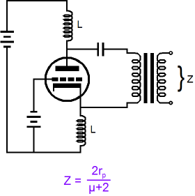
No they are the same. Anyway, the transformer is connected between the outputs so its sees only one output impedance; roughly 2/gm.Thanks, Merlinb.
-low output impedance, but source impedance of plate and cathode are different
A bit of audio mythology there...-cathode resistor only half the value of a cathode follower-> less negative feedback->better sound?
There may be a PSRR advantage but it depends on the overall circuit topology (hum cancellation).-true symmetrical output for better noise suppression
No, it is the same! The transformer is conected between the outputs!-half the output swing available compared to a tube voltage gain stage,
One thing we do not drawn in the schematic, is the capacitive coupling from the primary to the secondary.
Once you connect the secondary to the load (next stage or cabling to the next stage), that can cause the capacitance to have an effect.
That may affect high frequencies, and may affect the balance of the floating secondary.
Once you connect the secondary to the load (next stage or cabling to the next stage), that can cause the capacitance to have an effect.
That may affect high frequencies, and may affect the balance of the floating secondary.
With a true cathodyne the grid needs to be biased up to a higher voltage, so Ra and Rc can be made equal.
Unless, of course, he uses two identical chokes for loading the plate and cathode and their low DCR can set the bias for the cathode renders no need for an elevated grid as illustrated in the Broskie article. Of course that's a lot of irons (and expensive) for a real world project.
===============
*** off topic ***
Can someone tell me if the gain of the cathodyne like the above example can change if I apply variable negative voltage to the grid to change the bias current if the tube is a remote cut off triode in a compressor circuit? I want to find a way to do compression without resorting to a conventional push-pull circuit.
Last edited:
Using chokes does not eliminate the fact that there is also distributed capacitance across the chokes, and they are connected to the output transformer that has capacitance from the primary to the secondary.
In an ideal floating world, all kinds of wonderful things can happen.
But then at some point, an input signal source that connects to the input of this line amp, a power amp that connects to the output of the line amp, or some other device like the capacitance to free space of a 100 foot long speaker cable connected to the amplifier,
may causes the total system to be anything other than "floating".
Parasitics are just that, they are a parasite.
We do not like them, but they do exist.
You see a perfect part, I see parasitics.
Last edited:
Hello folks,
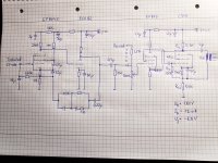
having drawn the complete schemo of the pre now.
Please have a check whether its principal OK.
Output tube is Siemens C3M like in the Shindo Vosne models.
Hoping for a circuit that gives excellent results.
Outputs can be Sowter 1010e or Jensen parafeed etc.
PSU will be sufficient voltage with 280 VAC. Same as Shindo.
Don't want to use chokes.
C3M is fine without heater elevation.
Attachments
Last edited:
- Status
- This old topic is closed. If you want to reopen this topic, contact a moderator using the "Report Post" button.
- Home
- Amplifiers
- Tubes / Valves
- Cathodyne tube line pre