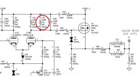
Albert - I believe you have it correct - the 475K grid leak resistor should be on the other (downstream) side of the 141 2.1k grid resistor to match the other side- I think someone had flagged this issue on a previous thread on another site.
There are a couple things that are not same as what I see on internet, but who knows which one is correct......
On the right channel, the 475K resistor is between 1.1K and 1uF of INPUT+. So the first modification to do is to make both channel be same.
- The opamp is there as a servo to zero the headphones output.
- The heater is used as a resistive load for the headphones output's darlington.
Thanks for the answer, it makes sense.
However, was that a good to power the heater as a resistive load by headphone output? Could the headphone signal crosstalk with input signal? They are not phase matching exactly.
If we modify it to power the vacuum tube heater with constant 6.3V, and add a fix resistor load on headphone output, should that make sound better?
It is a good idea to use the heater as a load for the output buffer. There isn't enough interaction between the heater and the rest of the tube to be detrimental to the sound in practice (I've used a similar scheme). The advantage is that you save some power and quite a bit of heat in the box.
It is a good idea to use the heater as a load for the output buffer. There isn't enough interaction between the heater and the rest of the tube to be detrimental to the sound in practice (I've used a similar scheme). The advantage is that you save some power and quite a bit of heat in the box.
Thanks for comment again!
Sorry, forgot something. There is something that isn't too great with the scheme they use though: as you have only +/-6.3V rails, you don't get a lot of voltage output for the headphones. So it's best used with low impedance headphones.
Pete Millet for example in the starving student also uses the heater as load but he uses a tube with 19v heater.
Pete Millet for example in the starving student also uses the heater as load but he uses a tube with 19v heater.
It is a good idea to use the heater as a load for the output buffer. There isn't enough interaction between the heater and the rest of the tube to be detrimental to the sound in practice (I've used a similar scheme). The advantage is that you save some power and quite a bit of heat in the box.
I found some IXYS MOSFETs commented for audio amp application. Nowadays not many discrete semi manufacturers still making linear MOSFET. On the datasheet attached, looks they did lots of tests for linear operations. However, I never heard big brand used IXYS FET. Does anyone have experience with them?
Attachments
Sorry, forgot something. There is something that isn't too great with the scheme they use though: as you have only +/-6.3V rails, you don't get a lot of voltage output for the headphones. So it's best used with low impedance headphones.
Pete Millet for example in the starving student also uses the heater as load but he uses a tube with 19v heater.
Yes, in the Stereophile review Wes used Grado to test the headphone amp. In my experience, Sennheiser is also easy to drive. I never tried planar headphones but I heard they were power hungry that may challenge Melos headamp.
Melos SHA-Gold headphone amplifier | Stereophile.com
I found some IXYS MOSFETs commented for audio amp application. Nowadays not many discrete semi manufacturers still making linear MOSFET. On the datasheet attached, looks they did lots of tests for linear operations. However, I never heard big brand used IXYS FET. Does anyone have experience with them?
Never mind, they are different FETs.
Albert - this is to replace the IRF510 follower?
Yes, that's my plan, any problem?
The IRF510 is vertical, while the 2SK is a lateral - does it matter?
I was going to build the exact circuit as best I could to see if I could get that linestage "Magic", minus all the stuff I am not interested in (headphones, LED Volume control, etc)...going to use your schematic instead of the one I found online.
Differences in our schematic:
The dual series plate resistor (I actually never confirmed there was a second 18k series plate resistor)
Cathode diode...how do I get my measured 5v across a single 1N4148? Were there seven of them in series?
Last edited:
I just noticed the pinouts of two MOSFETs are not same. Was that what you mean about vertical/lateral? Thank you for remind that.
- The dual series plate resistor
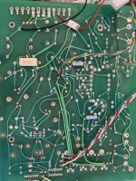
I did carefully measure in the circuit and main time I reference to Melos manual circuit. I did notice the differences and double checked the plate resistors, I could not see another series resistor there, at least on my board. Also in theory, I don't think a series resistor is needed.
- For the 1n4148, honestly that was my guess. It states on the manual a switching diode, and physically it's a glass package axial part, I searched over, it very likely a popular 1n4148. However, if you seen 5V across that diode, then it was definitely not a switch diode, not a zener neither, because it was forward bias. It may be a bi-direction zener to protect the tube from high grid voltage. I will check that after I put the board back to the system.
- The dual series plate resistor
I did carefully measure in the circuit and main time I reference to Melos manual circuit. I did notice the differences and double checked the plate resistors, I could not see another series resistor there, at least on my board. Also in theory, I don't think a series resistor is needed.
- For the 1n4148, honestly that was my guess. It states on the manual a switching diode, and physically it's a glass package axial part, I searched over, it very likely a popular 1n4148. However, if you seen 5V across that diode, then it was definitely not a switch diode, not a zener neither, because it was forward bias. It may be a bi-direction zener to protect the tube from high grid voltage. I will check that after I put the board back to the system.
- Status
- This old topic is closed. If you want to reopen this topic, contact a moderator using the "Report Post" button.
- Home
- Amplifiers
- Tubes / Valves
- Melos SHA GOLD Line Stage