Hi, banpuku
Something is odd here. 275 V is between cathode (filament) and Anode (plate). With automatic biasing (1k5 cathode resistor), you need to add 50 V Cathode voltage (1k5 x 34 mA) to your 275 V to get your anode voltage relative to the mass (ground). Add 5 more volts of voltage drop due to the DC resistor of your primary’s output transformer. So you want 330 V B+ (DC power supply).
As you’re learning the valve maths, I suggest a more conservative 45 biasing point. Use standard 250V/34mA, i.e. use 305 V B+ With 1K5/10W non inductive cathode resistor.
Regards, Jerome
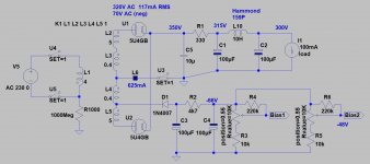
Here is the latest version of the schematics.
1. The power supply is currently a CLC, but I am strongly leaning towards an LCLC.
2. C3G operating points changed 170V : 14mA. Not sure if we have enough amps here, so any thoughts are encouraged.
3. 45 operating points changed to 275V : 36mA. This is in line with the maximums on the RCA 45 data sheet.
Something is odd here. 275 V is between cathode (filament) and Anode (plate). With automatic biasing (1k5 cathode resistor), you need to add 50 V Cathode voltage (1k5 x 34 mA) to your 275 V to get your anode voltage relative to the mass (ground). Add 5 more volts of voltage drop due to the DC resistor of your primary’s output transformer. So you want 330 V B+ (DC power supply).
As you’re learning the valve maths, I suggest a more conservative 45 biasing point. Use standard 250V/34mA, i.e. use 305 V B+ With 1K5/10W non inductive cathode resistor.
Regards, Jerome
Last edited:
I do not own any C3G tubes yet. I am open to other suggestions for the driver tube. If I stay with the C3G tube, one of the other operating points to consider is 170V : 14mA : -2.4Vk. If you have any other driver tubes (triode preferably) then please suggest with operating points. I am all ears.
Good stuff. Keep it coming.
I have my own "stash" of C3g tubes. I have used them in a variety of applications. By far the best application for this tube/valve might be a headphone amplifier.
They are crazy expensive now. I paid around EUR 15 to 18 apiece for a few small lots of NOS ones some years ago, and that was already kind of pricy. In those days, not too many people liked using loctal sockets.
Today they go for silly prices. I should probably sell my small stash to fools on that 'bay site and buy some cheaper unknown stuff.
The other "pentode wired as triode" contenders are D3a, E280F, E180F, E810F, PL802 etc.
There are of course others. Any pentode can be wired in triode.
High Gm driver pentodes
I hear EF184 is nice. 6JC6 triode connected has gotten nice reviews, but I have not seen any measured plate curves.
There might be some triodes too... Don't forget them. EC86 for example is a very nice triode, with not terribly high internal resistance.
Maybe some nice (and less expensive) Russian tubes would be worth looking at as well.
Ian
Hi, banpuku
Something is odd here. 275 V is between cathode (filament) and Anode (plate). With automatic biasing (1k5 cathode resistor), you need to add 50 V Cathode voltage (1k5 x 34 mA) to your 275 V to get your anode voltage relative to the mass (ground). Add 5 more volts of voltage drop due to the DC resistor of your primary’s output transformer. So you want 330 V B+ (DC power supply).
As you’re learning the valve maths, I suggest a more conservative 45 biasing point. Use standard 250V/34mA, i.e. use 305 V B+ With 1K5/10W non inductive cathode resistor.
Regards, Jerome
Yes Jerôme, you are right... his last schematic does not make sense.
Here is a short primer:
1. Look up the nice RCA specs sheet for the 45 tube. go down to the average plate curve characteristics.
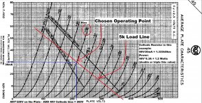
2. Take a screenshot of it. I use old-skool software like MS Paint. Then draw a 5k OHM load line. 300V/5kOhm = 60mA. Draw a straight line between 300V and 60ma.
3. Now you can move that load line around in Paint. Look at where you want it to bias at, current, etc. Check to see if you are (hopefully) in a safe operating region with lots of linearity.
4. Don't forget that for cathode bias, your cathode resistor value will be calculated based on the idle current and the bias voltage you will need. Learn Ohm's law very well.
5. Don't forget that for cathode bias, your actual Plate voltage will be whatever the value you choose from the Plate curves PLUS the cathode bias you choose.
6. You will likely find that the perfect value cathode resistor does not exist. You need to use standard values... Then you need to go back and work on it to fit the cathode resistor you are able to source.
7. Once you figure all this out, go back to your Power Supply. You can use PSU II to see if it will work. Hint: It probably won't. Then you will need to go back and re-juggle things again. Or maybe source a different mains transformer. Everyone in this hobby has a bunch of JUNK collected from things that could not be made to work. After a while, you learn to work out EVERYTHING very meticulously before you buy anything.
7a. When you get very good, you find ways to finally use the JUNK. Ok.. I continue on now:
8. If you have VERY good data on your mains transformer, you can correctly populate the transformer properties in PSU II. Then PSU II will deliver fantastically accurate results. Some Transformer manufacturers deliver GREAT specs sheets. Some do not though... In that case you will need to do measurements to get accurate values for PSU II.
8a. When using PSU II, you can also enter more correct ESR values for Capacitors. Modern Film caps have very low ESR. Also make sure you get the correct data for you choke in PSU II. You can also find ways to put in your bleeder resistor (make sure it is rated high enough). Its a lot of fun!
")
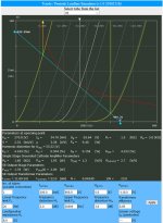
Here, I just made this as an example using the RCA plate curves. Don't just use these values - figure out your own please. I chose the values to make the math simple, but you might find it challenging to find a 1.333kOhm cathode resistor. Just sayin'
Attachments
Last edited:
Here, I just made this as an example using the RCA plate curves. Don't just use these values - figure out your own please.
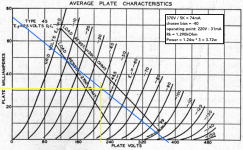
Great stuff, thank you. I am learning so much. Here is my attempt at the operating point. I did this on my own, so it is slightly different than your curves and operating points, but close enough to make me feel somewhat confident.
Please let me know what you think.
Also, a few follow up questions:
1. power = Rk * 3. I am assuming this is the wattage of the 1.29k resistor, correct?
2. Using my operating points (see attached), plate voltage = 220V + 40V = 260V. Max plate voltage for 45 = 300V, so we should be good. Please confirm.
Thanks, Pat
Attachments
I think you are getting the idea.
The good news is that tubes/valves are a bit "forgiving" so you could use a 1.3k ohm cathode resistor in your example. Maybe you will have a chance of finding this value.
Then make the cathode resistor 5 Watts. it doesn't hurt to over-spec this.
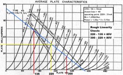
Don't think that your amp totally follows that load line. It doesn't. Think of it like an oval cloud around that load line. nonetheless, my next thing is to do what I call a "rough linearity check"
I pick some equal distance bias points on the load line and see how equal the plate voltage values will be. This load line is not too bad. You can see that you can swing a lot of volts at the little 45 Tube and it should be quite "linear" (from the specs sheet at least).
There is more here to consider. This is only a rough check. If it fails the rough check then you need to consider a different operating point, output transformer primary inductace, etc.
The good news is that tubes/valves are a bit "forgiving" so you could use a 1.3k ohm cathode resistor in your example. Maybe you will have a chance of finding this value.
Then make the cathode resistor 5 Watts. it doesn't hurt to over-spec this.
Don't think that your amp totally follows that load line. It doesn't. Think of it like an oval cloud around that load line. nonetheless, my next thing is to do what I call a "rough linearity check"
I pick some equal distance bias points on the load line and see how equal the plate voltage values will be. This load line is not too bad. You can see that you can swing a lot of volts at the little 45 Tube and it should be quite "linear" (from the specs sheet at least).
There is more here to consider. This is only a rough check. If it fails the rough check then you need to consider a different operating point, output transformer primary inductace, etc.
Attachments
Last edited:
Honestly though.. I am thinking it would be worth considering to have no cathode resistor and use fixed bias for your project.
Single ended amplifiers with nice LCLC power supplies are very addictive.
I hate the idea of using a cathode resistor/capacitor for auto-bias. So, yes I like the idea of fixed bias. Now I need some help. I did a search to learn about fixed bias. The part I don't understand is how the grid is supplied with the correct negative bias voltage. How is this achieved?
You hook it up to the negative voltage supply of your choosing.
kind regards
Marek
My power transformer has a 70V tap. Is this the appropriate voltage source for the fixed bias? Only part that confuses me is whether it is negative or positive voltage. I don't have the transformer yet (being shipped), so can't measure. That said, does the 70V, which comes after the 0 (zero) mean that it is negative voltage? Here are the power transformer specs:
secondary : 320V~280V~0~70V~280V~320V AC0.16A DC CT tube160mA
It's AC voltage - you can make it positive or negative, whatever you like.Only part that confuses me is whether it is negative or positive voltage. I don't have the transformer yet (being shipped), so can't measure. That said, does the 70V, which comes after the 0 (zero) mean that it is negative voltage?
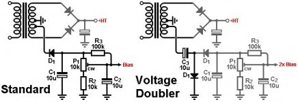
Something like that would be appropriate:
Attachments
It's AC voltage - you can make it positive or negative, whatever you like.
Something like that would be appropriate:
TG: thanks. Looks straight forward. Would the DC bias then feed into the negative leg of a grid leak resistor? And if so, would the grid leak resistor value be changed to adjust the negative bias voltage? In my case, I have a -70V tap on the transformer. I need -40V bias. So, need to adjust the voltage by 30V.
Yes.Would the DC bias then feed into the negative leg of a grid leak resistor?
No, the bias voltage is adjusted by the P1 potentiometer.And if so, would the grid leak resistor value be changed to adjust the negative bias voltage?
For the voltages you have you should use the first schematics (no need for doubling). I'd add another 10k constant resistor to the upper leg of the P1 (the other leg of this resistor goes to C1/D1/R3 connection point).
Also I'd up the C1 and C2 values to at least 47uF (C2 could be even bigger) - 10uF ones give too much bias voltage ripple, it ain't no good.
Last edited:
I don't like common bias supplies either.I don’t know, personally I’ve always been skeptical of a common PSU for fixed bias.
But OP mentioned in his first post that he is building the amp as monoblocks, so the supplies will be separate anyways
If he want to use fixed bias, the B+ can't exceed 275-280V.
Triode / Pentode Loadline Simulator v.1.0 (20161216 www.trioda.com)
Triode / Pentode Loadline Simulator v.1.0 (20161216 www.trioda.com)
Attachments
Hi euro
I think he knows this now. For fixed bias, he needs to remove that 1st cap in his PSU, or at least significantly reduce its value.
I look forward to what he comes up with
Ian
Hi team - I received my power supply parts today. For this first round, I am going with the simple schematic: Type 83 rectifier --> CLC (10uF - 10H - 50uF). Using the 320Vac secondaries, B+ is measuring 450 Vdc. The power transformer is built for 120Vac primary, but my mains (from the wall) is 123.5 Vac. So, B+ is a bit higher. No complaints here. The power supply transformer is dead silent. So is the choke. Both are ISO Tango products.
I will adjust the B+ voltage going to the plates based upon the final operating points. Chosen. In addition to some NOS 45 and 50 tubes, I also have a EML 45B on its way. I may try the 45B with the higher plate voltage, as it is spec'd up to 420V. B+ is 450V, bias is TBD (will be greater than 30V) so the voltage should fit within the EML 45B specs.
Q: Using a DMV, is there a best practice to measuring AC ripple after C2 in the CLC power supply?
Thanks,
Pat
I hate the idea of using a cathode resistor/capacitor for auto-bias. So, yes I like the idea of fixed bias. Now I need some help. I did a search to learn about fixed bias. The part I don't understand is how the grid is supplied with the correct negative bias voltage. How is this achieved?
Sorry, I was away a few days. Yes, the grid voltage must be negative.
I see that others have provided some schematics. These work if you have a bias "tap" off the B+ mains winding.
Or do you have a totally separate bias winding?
- Status
- This old topic is closed. If you want to reopen this topic, contact a moderator using the "Report Post" button.
- Home
- Amplifiers
- Tubes / Valves
- C3G drives 45