Hello Forum,
I am new here - been a professional engineers in research (audio compression), with an amplifier manufacturer (R&D in digital and analog Audio) and the last 20 years in the digital communications industry.
I have grown tired of my high end system with narrow baffle, high resolution sound. Now gradually building up a system that it fun to listen to (I have two Audio Research D150 under restoration) and some big JBL studio monitors - actually making a system from the period in audio when I thought listening to music was fun and gave a you a feeling of being subjected to something which touched you emotionally.
In connection with restoring the D-150's (I do that absolutely without compromise - respecting also the period of the equipment), I have noticed that the magazine "The Audio Amateur" has a sort of review of the D-150 in issue 2 1984 (Classical schematics). I do not have this article (naturally I have the schematics and the parts-list), but I wonder if some additional text goes together with this in the magazine.
Is there someone out there whom could be willing to depart with this issue - or just a copy of the article? I would be a very happy receiver/purchaser.
Thank you and best regards
Morten
P.S. If anyone is busy with a D-150, I have found an error in the construction which is present on both of my amplifiers (the high impedance feedback from the primary of the output transformer back to the drive V9 (&V10) is connected in in-correct phase for the right channel - thereby introducing a slight positive feedback instead of the negative feedback as intended by the design)
Welcome to the forum Morten.
Pictures of the amp for the curious?
I went thru a similar move some 20 years ago, but headed in a slightly different direction. But it is much more fun and enjoyable.
I did have that issue. I don’t know whether it has survived, but i can check. Have you contacted aXp? they may also be able to provide it.
dave
Thanks for the responses. If you could find the magazine, wonderfull - but I will try as you suggested as well.
Indeed, the ibput LP-filter is just to make square-waves look better, the am absolutely sounds better without it. BTW, I am also going to run them balanced - the entire amp, except for the phase-splitter in one half on the input, is fundsmentally a balanced design. To my judgement, quite advanced for the period - impedance-levels and everything quite well designed - output tubes are opersted quite hot; I hope modern 6550's still has the required robbustness.
I will surely post some pictures - but be patient, I only engage myself with my audio when I sm relaxed and in the mood to do it - it is a hobby; and I want it to remain enjoyable")
Indeed, the ibput LP-filter is just to make square-waves look better, the am absolutely sounds better without it. BTW, I am also going to run them balanced - the entire amp, except for the phase-splitter in one half on the input, is fundsmentally a balanced design. To my judgement, quite advanced for the period - impedance-levels and everything quite well designed - output tubes are opersted quite hot; I hope modern 6550's still has the required robbustness.
I will surely post some pictures - but be patient, I only engage myself with my audio when I sm relaxed and in the mood to do it - it is a hobby; and I want it to remain enjoyable
Bill's amplifier circuit was carried over from Electronic Industries, and the Dual 100 and Dual 50.
In the ARC tube amplifiers up to 1976, the circuits were essentially all the same, differing mainly
in the power supply and output transformers. A few early versions lacked the cathode followers,
including the ARC Stereo 70 mod.
In the ARC tube amplifiers up to 1976, the circuits were essentially all the same, differing mainly
in the power supply and output transformers. A few early versions lacked the cathode followers,
including the ARC Stereo 70 mod.
Last edited:
Thanks for the information Rayma. The balanced design, the crosscouplers and the active loads... A petty they did not drive it differentially those days. Distortion is really quite low, the bandwidth not that large (albeit I find the power bandwidth good enough) - but, it IS some quite substantial output transformers (avoiding core saturation for the bass response), and they are probably hard to give much more bandwidth considering the stability required to drive some of the tougher electrostatic panels of the time...
Thanks for the information Rayma. The balanced design, the crosscouplers and the active loads...
A petty they did not drive it differentially those days.
Bill told me at the time (in 1975) that it would decrease sales and increase costs.
I didn't ask him why both RCA and XLR couldn't be provided. They were already doing
single-ended tri-amped Maggies with their tube electronic crossovers.
my D150 is still sitting since I gave up on troubleshooting one tube which does not bias. I still have the original tubes in all OP positions. I got busy with other projects but I am getting to a point where I will look at it again. My plan is also to run it balanced, though lately I have been thinking of maybe leaving it single ended if I decide to sell in a year or so (I have tons of good class A amps and the tube bastard is just huge). I will of course follow your work for any useful bits. Enjoy the hobby
Hello audiohead,
Thank you. I do have both the schematics and the parts-list. I am interested in any accompanying text that might be in the magazine. I.e. a desciptuon/analysis of the circuit etc. In case there is any additional information besides the schematics and parts-list, I would be very pleased to obtain a copy of this.
Br
Morten
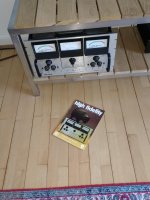
High fidelity
Hello DangSvend,
How Wonderfull that you mention it - I had all the high fidelity magazines back then (loved especially the Poul Ladegaard times) - unfortunately I have lost my issues in moving many years ago.
I do remember the issue with the D150, and would just love a copy of the article!
Would you be able to help me with this? i would very much appreciate that - indeed.
Going too slow with the renovation - I am baby-stepping, measuring transformers, finding most appropriate caps etc. Getting along, but slowly!
Br
Morten
Tubes
Hello Peter,
Actually I am a little ad odds here...
I have one set of NOS GE's - but only for one of the amps.
Output tubes are operated quite close to maximum specifications in this amp and I am a little afraid of the quality of what you can purchase today (vacum? Quality control?). Luckily both 6550 and kt88 are quite robust by design but, to the best of my knowledge, the original GE's had a slightly higher specification for plate- and screen- dissipation (42W and 6W) than any of the 6550' obtainable today.
BTW - prefer 6550 to KT88; just to let you know what kind of "sound" I favour.
Q: Is it your amp, Svend in the picture of the high fidlity magazine? - operating reliably?
Thanks guys and br
Morten
Hi Morten D150
I am a bit confused apparently i have also have the user name DangSvend.
anyway....
As you can see from the picture i also own a D150 so I am am looking forward to your progress.
I will scan the article and post it here as soon as possible.
Best regards
Erik
I am a bit confused apparently i have also have the user name DangSvend.
anyway....
As you can see from the picture i also own a D150 so I am am looking forward to your progress.
I will scan the article and post it here as soon as possible.
Best regards
Erik
For Erik
BTW Erik,
The amp is really not a toy; it is for grown ups (design wise). There are a total of three nested negative feedback loops.
In both of mine, one of the feedback loops, the "inner most" (from output tubes, plate to driver, cathode) is connected in incorrect phase for the right channel - effectively giving this loop positive feedback (and hence less stability margin). I am confident that this is NOT a design intention - it could be incorrect assembly during manufacturing (wires from the output transformed incorrectly mounted for the right channel), but I do find it strange that this mistake is identical on both my amps!
I will post you once I have confirmed the phases of the output transformers by measurements - manifesting that this is indeed the case.
If so, I will let you know which wires to interchange in order to obtain the intended circuit topology (and two identical channels). This ofcourse only if the same mistake is present in your amp.
Br
Morten
- Home
- Amplifiers
- Tubes / Valves
- The Audio Amateur #2 1984, Audio Research D-150