Hmmm, I would have expected the Op Amp would clean up the distortion better. Could the Mosfet capacitance be distorting the N Fdbk to R1?
I guess the output tube grid1 V variation (and so affecting the R2 current) is messing up the N Feedback to R1. Maybe connect the R2 to the Mosfet source terminal instead of drain, with a separate hi-value pull-up resistor for the Mosfet drain (or CCS pull-up).
I guess the output tube grid1 V variation (and so affecting the R2 current) is messing up the N Feedback to R1. Maybe connect the R2 to the Mosfet source terminal instead of drain, with a separate hi-value pull-up resistor for the Mosfet drain (or CCS pull-up).
Last edited:
Alternatively, just use a separate higher value R divider to supply the N Fdbk for the inverting input to the Op Amp. That would avoid output tube Vg1 effects and Mosfet cap effects too.
(the scheme above, post 43, would put more gain in the inner shunt N Fdbk loop, being just the usual CFB for the driver scheme, Mosfet source Fdbk there)
(the scheme above, post 43, would put more gain in the inner shunt N Fdbk loop, being just the usual CFB for the driver scheme, Mosfet source Fdbk there)
Last edited:
Hmmm, I would have expected the Op Amp would clean up the distortion better.
Yeah, me too. I did go back and try to figure out the major differences between my circuit and the circuit that I was inspired by. Jeff Macaulay used a BJT rather than a mosfet. At first, I thought he used a 60k grid bias resistor on the EL34 tube he used, but I noted that a correction was issued in a later issue. He used 560k grid bias resistors on the EL34s (is that violating spec?).
He also says he got 0.6 Ohm Zout on the amp he built with no feedback loop around the output transformer. This is the type of result one would expect with close to 100% voltage feedback. EL34s have more transconductance than these 6384s, so the 6384s are never going to have as low a Zout as the EL34s are capable of achieving, and everything is of course different since Macaulay's amp is push-pull. Still, I have built 30% and 50% feedback push-pull amps and I got ~2 Ohm Zout on the 30% feedback amp and ~1 Ohm Zout on the 50% feedback amp.
I used a FET to get rid of base current error, but it is possible that this was one of those improvements that makes things worse, and that base current error compensates for other errors in the output stage through fortuitous distortion cancellation.
Also, AC current flow into the grid bias resistor is undesirable and would mess up the feedback. I'm using 100k as per datasheet. Macaulay used 560k, which would cause a good bit less AC current to be pulled out of the feedback path.
My next step will be to implement a MOSFET follower in the loop to drive the grid (mostly to prepare for the transmitting triode, but also to quantify the improvement of shielding the feedback network from the grid bias resistor). My MOSFET gate bias resistor will be 3MOhm. I have Fairchild FETs with ~5pF Crss or a new CREE SiC FET with ~2pF Crss that I just bought to try. It has less transconductance than the Fairchild FET, though. Maybe I'll just stick with the Fairchild FETs I always use.
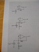
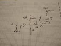
Here's a quick drawing with op-amps that shows what I'm trying to accomplish as far as the feedback scheme goes and how I'm hoping to improve things on the next iteration.
Top shows what I'm trying to accomplish here (but with a tube).
The middle picture shows what is currently happening with the 6384 grid resistor in play at AC. It looks a little similar to the standard non-inverting config, except driving the inverting side with a transconductance amp. The lower the resistance of the grid resistor, the lower the effect of the feedback.
I'm going to put a mosfet follower to buffer the feedback network from the grid resistance (and to supply grid current in a subsequent experiment). The mosfet gate bias resistor can be quite large, I've used 3M before without issue.
As you can see, the 100k resistor is a pretty heavy load for the feedback network. I'm expecting the jump to 3M to get the feedback ratio over 90%. The first test I will perform is a Zout measurement. If my calculations are correct, feedback over 90% with the 6384 should get me to a Zout less than 1 Ohm with OT losses factored in.
Mouser order arrives later today.
Attachments
While I see the concern over the grid resistor loading the N Fdbk, there is still a distortion factor coming from the current across the R2 220K Fdbk being proportional to plate V minus grid V. Grid V for an approx. square law device is not so clearly proportional to output V.
However, notice that the AC current thru the grid resistor is proportional to grid V (assuming no grid current). If the grid R were also 220K, then the bottom (gnd) end could be connected to the Mosfet source resistor to add the current back in to the R1 499 Ohm I sense resistor. (except for the DC bias V being wrong)
I think it would still be safer to just use a separate high R divider from the plate to ground to control the inverting Op Amp input, no Mosfet capacitance issues then.
Attachments
Last edited:
While I see the concern over the grid resistor loading the N Fdbk, there is still a distortion factor coming from the current across the R2 220K Fdbk being proportional to plate V minus grid V. Grid V for an approx. square law device is not so clearly proportional to output V.
However, notice that the AC current thru the grid resistor is proportional to grid V (assuming no grid current). If the grid R were also 220K, then the bottom (gnd) end could be connected to the Mosfet source resistor to add the current back in to the R1 499 Ohm I sense resistor. (except for the DC bias V being wrong)
I think it would still be safer to just use a separate high R divider from the plate to ground to control the inverting Op Amp input, no Mosfet capacitance issues then.
Ok, I see what you are saying. The original intention was to just make a near-perfect transconductance amp with the op-amp and mosfet, and use that as a baseline for comparison against tube circuits, but we have other options open to us if we keep the op-amp and play with other feedback arrangements.
There are a lot of things to try here.
We'll see how much performance we can ring out of the op-amp before moving on to tubes.
Last edited:
Probably the best system-level approach (if op-amps are permitted) would be to use an op-amp that can make the full grid input swing at its output (like an ADA4700) and just compare a sample of plate output to the amp input. It would be dead simple and very effective.
No glow from the op-amp, though.
No glow from the op-amp, though.
No glow from the op-amp, though.
Well, that could be changed . . . . . .
Attachments
Well, that could be changed . . . . . .
Yep.And that's the idea in the end: to come up with something that is simple and works well and uses tubes cuz its fun to make an amplifier with glowing parts.
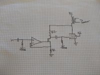
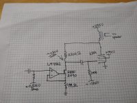
Here's the current schematic. I got it up and running last night.
I listened a bit and all I can really say is it sounded pretty good on my crappy test speaker, certainly no worse than it did before I installed the grid driver mosfet.
I did have a moment to measure Zout. It was ~1.1 Ohm (1.67 Ohm before the change). There's definitely more feedback than before.
I didn't have time to run distortion measurements. I'll probably get to that this weekend.
Attachments
What MOSFET are you using? What’s the actual grid voltage applies to your tube through the MOSFET?
Regards, Gerrit
Required grid bias for the output tube to sit at 75mA is ~-17.5V on the one sample we have been playing with.
The mosfet in the V-to-I converter is an FQPF2N90. I had only one left so this was a good way to put it to use.
The grid driver was a C2M1000170D that I bought to try out. Capacitances are quite low but transconductance isn't super high. I like the versatility that the 1700V rating offers, but it's a little pricey.
Good news is it doesn't seem prone to random oscillations or anything.
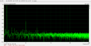
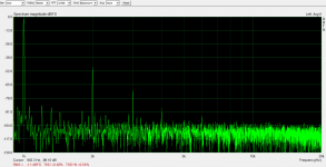
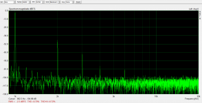
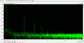
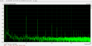
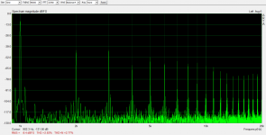
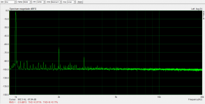
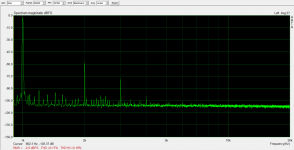
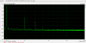
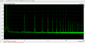
Attached are distortion measurements with the mosfet grid driver.
THD with Mosfet Driver
100mW: .071%
500mW: .17%
1W: .25%
2W: .36%
5W: .56%
10W: 1.22%
THD without Mosfet Driver
100mW: .21%
500mW: .48%
1W: .70%
2W: .99%
5W: 1.56%
10W: 2.83%
Definitely a worthwhile improvement.
THD with Mosfet Driver
100mW: .071%
500mW: .17%
1W: .25%
2W: .36%
5W: .56%
10W: 1.22%
THD without Mosfet Driver
100mW: .21%
500mW: .48%
1W: .70%
2W: .99%
5W: 1.56%
10W: 2.83%
Definitely a worthwhile improvement.
Attachments
Last edited:
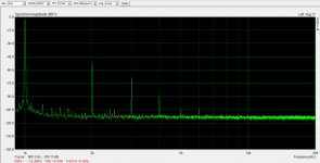
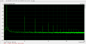
For comparison, here are results I got with a mosfet follower driving this same output transformer. I built a very low distortion voltage amp with a 1000V B+ and drove a mosfet set at 85mA quiescent current and 460V B+.
Power,----THD
100mW, .086%
500mW, .19%
1W,------.31%
2W,------.32%
5W,------.37%
10W,-----.46%
13.25W,--.81%
16.5W,--1.74%
18.6W,--5.06%
Zout - 0.6 Ohm
You can see that the huge gm of the mosfet gives a very low Zout, but distortion is comparable or sometimes even lower with the tube for lower power levels.
I suspect that the mosfet was driving the transformer with at least an order of magnitude less distortion than what was coming out of the secondary. I never got a chance to directly measure, but the driver was putting out less than .01% distortion at levels to drive the mosfet for 1W amplifier output, and I have no reason to believe that the mosfet would add much distortion to that. The driver distortion was less than .06% all the way to 320Vrms.
The transformer simply adds a lot of distortion, even when perfectly driven. I don't have a lot of experience with SE amps, so I don't know if the Edcor transformer distortion is typical, but I think the only ways to further reduce distortion with this transformer is to attempt distortion cancellation or to have feedback around the transformer.
The more I think about this, the more I think that single-stage feedback is a dead end for my current project. I think this approach could work very nicely with a higher-gm tube like an EL34 or KT88.
The 6384 doesn't have enough gm to get Zout low enough for my tastes, even with 100% feedback (and the 826, the tube I'm planning on eventually putting in there, is even lower). I'd like the contribution of the tube to be less than the contribution of the OT DCRs. I'll need feedback around two stages to accomplish this.
It was fun to try and I think the distortion results I achieved rival the best 300B amps that I have seen, and this probably has less than half the Zout that those amps do.
It's not a bad result, but I think that my current project will steer me to a pentode input stage and returning feedback from output tube plate to input stage cathode.
The OT resistance is fixed, so a little output current Fdbk could null that out. Trying to go further to null out the speaker R gets tricky though, oscillator city.
It might be fun to learn trying, but honestly ~1 Ohm Zout sounds great on all of the speakers I have. The OT resistances are contributing about 0.5 Ohms here, so I just want to get the contribution of the driving circuit to somewhere around that same ballpark.
Honestly, I'm doing this amp mostly for aesthetics and to try something different. If I were going for max performance I wouldn't be building a single-ended amp tube amp at all. I just decided I should do at least one SE amp and I want it to have better performance than the typical circuits.
I'm going to probably settle on an 826 for output tube mostly because it was affordable and looks really cool. I'm pretty sure I'm going to use 6BN11 in the input stage probably for the same reason. Cheap and pretty, and I can get a lot of gain from it. I'm going to need that gain to get the 826 Zout where I want it.
If I cared less about looks, I might build a scaled-up version of this with two EL34s (or any other tube with similar transconductance) in parallel as output devices. It would do 20+W at low distortion at the right operating point.
The thing I really don't like about the transconductance stage driver topology is that in order to do it with tubes I'm going to have to build more negative supply rails (and it will probably couple all PS noise directly into the grid circuit, unless I can find a good solution to that problem). It will really be much easier to do a series-applied feedback arrangement involving two stages, and it won't take any more supply rails than I already have.
I'm going to try the easy circuit next.
- Status
- This old topic is closed. If you want to reopen this topic, contact a moderator using the "Report Post" button.
- Home
- Amplifiers
- Tubes / Valves
- Shunt Feedback 6384 SE Amp