Hi,
I would like to ask some details on maximum plate dissipation, and related excess we can apply when designing loadlines.
From what I see from 90% of the amps dedicated to instrument amplification, tubes are set to stay below the max plate dissipation curve in the part of the loadline that conducts 100% of the signal, and below twice the max plate dissipation curve when the signal exceeds "class A" going to "class B" (see the classical Marshall 460 V and 34 mA fixed bias with 3k4 Raa for a pair of EL34).
I guess this can be acceptable because the tube is off for 50% of the time, so it can work at twice the power for half the time (integral over one entire cicle will be below max plate dissipation).
At the same time, alot of hi-fi amps do not exceed the max plate dissipation in any condition. This is because hi-fi are supposed to play continuously while instrument amps are supposed to have loud and quiet moments?
At what external parameters is max plate dissipation calculated?
No air ventilation and ambient temperature 25°C?
Forced ventilation (like in rack gear) of the tubes can increased it, in order to increase the safety margin of the tube while squeezing some more watts from a lower load?
Thanks in advance to everyone will partecipate.
The dissipation may be averaged over an audio cycle. So you can go over the line if you also go under the line.
Class AB guitar service is generally tougher than home hi-fi service. Gigging guitarists favor more sound per pound and learn to replace tubes so sometimes the tubes are worked hard; hi-fi guys (mostly) do not like trouble and drama so the amps are (sometimes) more conservative.
You MUST allow ventilation. Small tubes are rarely "fan cooled" because it does not help a whole lot (not designed for it like transmitter tubes). 25c or 40c makes little difference at usual tube temperatures. Tight-racked gear MUST move the air through the box.
Tubes are cheap. Transistors are cheaper. WHY do you want to abuse them to squeeze some more watts? Use more tubes. Or a small tube and a sand-state amplifier.
Thanks PRR,
you are right, I'm "new" to the forum and the question may allow some misunderstanding on the reasons behind.
I'm aware that sand is cheaper than vacuum, and I don't want to melt down any glass.
I'm also aware of the need for ventilation in general and forced ventilation in racks, as I build my guitar and bass amps since 2004, and I've two racks.
My main questions are:
- at which external parameters is max plate dissipation calculated?
- how forced ventilation can help increase this value, so that standard instrument amplification configuration can work with safer conditions?
I guess that the harder working conditions of the tubes were initially needed to be louder than others as you said, while nowadays those conditions remains because of how the amps sound in that configuration, and because "we did it like that since the 60's, it must be right".
I share with you all this 1954 document by Walter R. Jones where I've found some answers to my questions:
http://www.one-electron.com/Archives/Tube/TubeJournals/Jones 1954 Tube Envelope Temperature.pdf
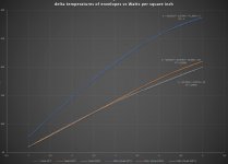
Envelope temperature should be kept below 175°C to increase the life of the analysed tubes.
I've plotted the variation in temperature between the ambient and the envelope, based on the amount of Watts per square inch.
http://www.one-electron.com/Archives/Tube/TubeJournals/Jones 1954 Tube Envelope Temperature.pdf
Envelope temperature should be kept below 175°C to increase the life of the analysed tubes.
I've plotted the variation in temperature between the ambient and the envelope, based on the amount of Watts per square inch.
Attachments
"at which external parameters is max plate dissipation calculated?" Load, but a speaker load is different to a resistor, it's impedance varies with frequency, also music content isn't the same as a sinewave. Also if running in class AB1 the valve is switched off some of the time and won't be dissipating full power 100% of the time.
So, if we design an amp for the max 25w power dissipation into a 8 ohm load, then build and test it with a sinewave IP, we'll get about 14v RMS across the load. If you put your meter across a speaker then turn it up quite loud whilst playing music, you won't see anything like this. Therefore unless your going to be listening to sinewaves there's no need to worry too much. Make sure valves are well spaced out and drill holes around the valve base to encourage air flow.
On my 120w monoblocks that use 6 EL34's I use a fan to blow air up through the chassis as the chassis got very hot without it, it's not just the valves themselves whose temperature you need to be concerned about. A good amp design will take into account quite a few different and often competing parameters, there's a lot to think about. A lot of these things only become apparent when you actually build the amp.
I looked at an EL34 datasheet, no where is temperature listed in the limiting values table. A valve is supposed to get hot, cooling it too much can effect it's efficiency.
Andy.
Last edited:
Thanks for your intervention Andy, indeed in my calculations I consider the valve "on" for 55% of the time, and maximum dissipation should be around 2/3 of the full signal. I also agree that real impedance of the speaker is higher than nominal most of the time (low resonance and high frequencies) except in the mids where is usually lower.a speaker load is different to a resistor, it's impedance varies with frequency, also music content isn't the same as a sinewave. Also if running in class AB1 the valve is switched off some of the time and won't be dissipating full power 100% of the time.
I would prefer to mount on chassis most power dissipating components (EG mosfets for CCSs and Powerdrive, resistors with high currents through them, etc...) that must be internal, and a (or more than one, if needed by the layout) heat sink on the external side of the chassis, then use a fan to blow air to the output tubes and heat sink. That's because I'm worried about dust accumulation inside the chassis.Therefore unless your going to be listening to sinewaves there's no need to worry too much. Make sure valves are well spaced out and drill holes around the valve base to encourage air flow.
So it could be needed to calculate approximately the amount of air to cool down a certain amount of power by forced convection around the tubes (irradiation is quite low I would say, because central tubes in your sextet "see" other EL34s for 3/4 of the lateral surface, and the getter being mirror do not irradiate), in order not to cool them down too much. I would say that as a starting point I can check what stardard product do and see if there's a correlation of factors.I looked at an EL34 datasheet, no where is temperature listed in the limiting values table. A valve is supposed to get hot, cooling it too much can effect it's efficiency.

zintolo,
Post # 7:
Your tube data sheet is a good point for discussion.
Maximum ratings:
Anode dissipation 40 Watts
G2 dissipation 5 Watts
G1 dissipation 1 Watt
Envelope temperature 200 degrees C
46 Watts, right?
Wrong.
Filament 12.6V @ 0.85 Amps = 10.7 Watts
That makes the total dissipation 56.7 Watts.
But be careful . . .
It is a general rule that if you run a tube with all the dissipations at maximum,
the tube life will shorten.
And, some tubes require a lower resistance maximum G1 resistor, when the tube is operated at high dissipation.
Example: KT88 https://frank.pocnet.net/sheets/084/k/KT88_GEC.pdf
You can see in the data sheet that for more than 35 Watts in the plate + screen, does require a lower grid resistor,
even though the plate by itself is rated at 40 Watts.
Last edited:
Thanks for your reply 6A3sUMMER,
Perfect, this is the maximum power that can be dissipated independently by every single part of the tube, with optimal external conditions (or probably Normal conditions).Maximum ratings:
Anode dissipation 40 Watts
G2 dissipation 5 Watts
G1 dissipation 1 Watt
This parameter is a further limit to previous ones: stay within previous limits, AND do not exceed that bulb temperature, otherwise lifetime of the tube will be shortened as well.Envelope temperature 200 degrees C
Well, this ça va sans dire, it is implicit in the working condition of the tube, and it is part of the previous limit: it would mean to do useless calculations all the time to include heaters power into the max dissipation of the tube.46 Watts, right?
Wrong.
Filament 12.6V @ 0.85 Amps = 10.7 Watts
That makes the total dissipation 56.7 Watts.
Yes, this is logic, because you increase the internal temperature (so the bulb one, that is the one you can easily measure) above the limits.But be careful . . .
It is a general rule that if you run a tube with all the dissipations at maximum, the tube life will shorten.
Good to know it, I wasn't aware of it. What is the physical reason behind this?And, some tubes require a lower resistance maximum G1 resistor, when the tube is operated at high dissipation. Example: KT88
As the tube gets hot, there are various factors that can cause grid current, or other problems.
The tube can go into thermal run-away, and destroy itself, and/or the amplifier parts.
Think of thermal run-away as thermal positive feedback. The hotter I get, the hotter I get.
Notice that for fixed bias the max G1 resistance is lower, versus the max G1 resistance for self bias operation.
If you look at lots of schematics, DIY and even commercial amplifiers, there are some designers who choose to ignore the max G1 resistance rules.
And . . . you will find threads on this forum with complaints like: "My amplifier burned out".
Then, you discover they had G1 with resistors more than the maximum spec.
Others claim that they have an identical amplifier, and that their amp works great.
Then I point out that "your mileage may vary".
Not all tubes of the same type/nomenclature are equal when it comes to maximum specs, versus reliability.
Sometimes even from the same manufacturer.
Think of a tube that has the filament voltage at +10% (allowed), Plate dissipation at maximum (allowed), and G2 dissipation at maximum (Allowed).
With all that heat surrounding G1 and G2, would you want to be stuck in there?
What if your sports car is rated for 7000 RPM, you like to drive at that RPM, but you waited for the maximum recommended miles to change the oil and filter? Is there a problem here?
As tubes get hot, sometimes the metals out-gas. How about if the Getter has been all used up (usually appears white, not silvery)?
Last edited:
Thanks 6A3sUMMER,
what is the impact of the grid leak resistor on grid current due to overheating?
and what are the factors that you are mentioning behing the lower needed value?
Thermal runaway at 200°C seems unrealistic, are you sure?
10% more voltage will not cause 21% increase in power, but way less to increased resistance of the heater (I've no info on this specific data for GU50), and this has to be considered on something that is 18% of total heat, it's few percentages more: not the major causes of heat or temperature increase for the tube.
I've done some calculations on the impact of forced ventilation on bulb temperature.
I need to find right coefficients for heat exchange based on air velocity, but around 2 m/s seems a good starting point to select the fan.
This can happen even without signal present, just the quiescent current in the tube.
Grid current into the grid leak resistor causes a voltage. Often, and every time I have observed it, the voltage is more positive (or less negative).
A positive (or more positive than the fixed bias) voltage on G1 will cause more G2 current and more plate current. So, the tube heats up some more.
Now, there is even more grid current. So, G1 is more positive (or less negative), So the tube heats up some more.
Do I need to repeat that a few more times. Run-away.
Sometimes gas in the tube causes G1 current. Sometimes more heat in the tube causes G1 current. Once grid current is on the increase, we may get into trouble.
This is what may happen with the amp just sitting there, powered up and warm.
Grid current during signal peaks may or may not be a problem (lots of variables).
That is another set of stories.
I have an inexpensive Infra Red meter. I am not sure of its accuracy, but I have glass tubes that sometimes reach up to 250 degrees Fahrenheit.
Power tubes maximum glass temperature varies widely, especially some high power RF tubes.
In general, Audio output tubes plates are not supposed to glow red.
Many RF power tubes are made to run that way.
Last edited:
But only if the tube is broken, or the bias circuit fails, not in standard conditions, right?This can happen even without signal present, just the quiescent current in the tube.
This happens when grid approaches the same voltage as the cathode (a bit before and beyond, of course), because the grid receives electrons from the cathode. But not in quiescent mode.Grid current into the grid leak resistor causes a voltage. Often, and every time I have observed it, the voltage is more positive (or less negative).
it is clear to me what a divergent process is, but it is not at idle as you were saying. That's why I don't understand your answer to my question.A positive (or more positive than the fixed bias) voltage on G1 will cause more G2 current and more plate current. So, the tube heats up some more. Now, there is even more grid current. So, G1 is more positive (or less negative), So the tube heats up some more. Do I need to repeat that a few more times. Run-away.
Well, what you describes is not happening in normal conditions at the amp at idle as you are saying.This is what may happen with the amp just sitting there, powered up and warm.
That is 121°C, that's actually very low for a tube, I see common values between 200 and 250 °C.I have an inexpensive Infra Red meter. I am not sure of its accuracy, but I have glass tubes that sometimes reach up to 250 degrees Fahrenheit.
I know from experience that tubes do go into thermal run-away, without any signal applied.
They also do that with small signal operation (many times less than full output).
I have actually watched the tube current go up, and up, and up without any signal present
(with the tube well within its recommended voltage, current, and dissipation limits).
And then, I turned the amp off, removed the offending tube, and trashed it!
Amplifier burnouts can be expensive, especially if you burn out an output transformer.
The tube is going to die (already is no good) and there are other parts failure modes too.
I have also had an amplifier with a grid resistor that was too high.
I listened to it for a long time, and everything was fine.
But then one day, and at moderate volume, it started sounding distorted, and the plate was glowing red!
I turned the amp off.
After the B+ was discharged, I changed the grid resistor to a legal value for that output tube. The amp worked perfectly after that, but only because I turned the amp off quickly.
Your mileage may vary.
Oh, I think you are thinking of G1 current as when the tube is operated in class A2, AB2, or B2.
The grid current I am talking about is Not that.
I am talking about 2 other things, grid current caused by a gassy tube, or by hot and large dissipation levels.
Remember, grid to cathode voltage is a relative thing. If the cathode is at +45V, and the grid is at 0V, the bias is -45V.
Or, if the cathode is at 0V and the grid is at -45V, the grid bias is the same . . . -45V
If the grid goes more positive by 2V, than the bias is 43V, so the tube current goes up.
The bias of either fixed bias, or of self bias, is the relative grid to cathode voltage.
Self bias has some limited automatic range of keeping the plate current from going up too high.
Fixed bias does not have a method of automatically keeping the plate current from going too high.
That is why the maximum grid resistance spec is higher for self bias than for fixed bias.
Last edited:
Thanks 6A3sUMMER, but here you are talking about faulty tubes or your mistakes in the design. It is normal to have troubles.
This last point can be solved if you have a low impedance driver, even if the grid leak resistor is higher than specs.
For this topic, this thread is full of useful information:
Amplifiers that exceed grid leak resistance
I have actually watched the tube current go up, and up, and up without any signal present and then, I turned the amp off, removed the offending tube, and trashed it!
I have also had an amplifier with a grid resistor that was too high. It started sounding distorted, and the plate was glowing red!
This last point can be solved if you have a low impedance driver, even if the grid leak resistor is higher than specs.
For this topic, this thread is full of useful information:
Amplifiers that exceed grid leak resistance
zintolo,
You said: "This last point can be solved if you have a low impedance driver, even if the grid leak resistor is higher than specs".
No, that is not true. Be careful.
The maximum grid resistance has to be measurable from the grid to return (usually amplifier ground) as measured on a DC Ohmmeter.
The maximum grid resistor specification in the tube data sheets has nothing to do with the driving impedance. Impedance is an AC term (which can include one, two, or three of these: R, C, and L).
Also, if you use fixed bias, you need the resistance from the grid to the fixed bias voltage to be within the maximum tube specs. That total resistance has to include the bias (voltage) resistance to ground/return.
Direct coupling to the grid is usually low resistance (depends on the circuit parameters).
Direct coupling from a low DCR secondary of an interstage transformer that has one end at ground/return is low resistance.
RC coupling to the grid, with a high resistance R is not a low resistance.
Do you see the difference?
zintolo,
You have observed that I run my tubes quite cool.
I think the highest I ever measured since I got the IR meter, was 275 Fahrenheit.
It is pretty obvious that I do that by keeping the dissipation down.
I listen near field (1 meter or less from the speaker to me).
I do not need lots of power from my amplifier.
And the amplifier is very near to me too.
In some rooms, the amp and speaker is in a corner, and with other heat generating devices there, like a computer and a printer.
I want the room to stay cool, even in the summer.
And that is part of my identifier, 6A3sUMMER. The SE 6A3 amplifier I built was made to run cool for Summer listening next to the amp, and all the other heat generators that were there too.
A few summers before that one of the amps I built was a low power SE triode wired 807.
I also am able to keep some of my power transformers running cool, by using Choke input filters for the B+.
These amps run for hundreds or thousands of hours.
Last edited:
Just a few observation to keep in mind... Idle plate dissipation may be really hot in some amps, however, when running signal the plate dissipation can be much lower... Also keep in mind the power supply on these guitar amp[s practically falls on it's face when pushing signal.. SO when drawing up the load-line, this would apply to the voltages at full power output.. For example I have a Marshall 100W that idles at 500V Plate 498V Screen.. WHen the amp is at full "clean" sine wave output the plate is around 430V the screens are at 400V .. roughly... SO you can see the operating voltages are totally different than idle...therefore the average plate dissipation will be much lower than idel..also taking into account the load-line path...is not linear ...elliptical ..
zintolo,
Look at Post # 2 from the thread you referenced:
Amplifiers that exceed grid leak resistance
Post # 2 of that thread said:
----------------------------------------------------------------------------------------------------------
"High grid leak resistors can mean short valve life. A bit of gassiness leads to thermal runaway.
Two options:
- use a lower impedance drive stage which can cope with a smaller grid resistor value
- use a different output valve which is happy with a high grid resistance (e.g. EL34)"
-------------------------------------------------------------------------------------------------
Please understand, the advantage of the lower impedance drive stage is that it is able to properly drive the smaller grid resistor value (as in now you can use a grid resistor with a lower value that within the tubes specification).
One reason designers use high resistance grid resistors, is that they can use a wimpy high impedance driver to drive it.
And, they can use a smaller less expensive coupling cap. Those are wrong ways to do it.
Instead, use a strong driver that has low output impedance so that it will be able to drive the correct grid resistor of the next stage.
And with the lower grid resistance, use a coupling capacitor that has enough capacitance to pass low frequencies to that grid resistor, so you can get good low frequency response.
Last edited:
Hi 6A3sUMMER, two decades as a moderator before and admin later in different forums, made me learn that, in every lenguage we speak, when this kind of sentences comes up, the mood of the people speaking is not as it should be.Do you see the difference?
This is not the way I want this thread to go on, so if you have felt offended in any way by my comments on your replies, I would ask you to tell me where not to repeat the issue with you, and in any case I do apologize in advance.
I understand your point, but the thread is not about running tubes at low current, nor to discuss about faulty tubes or wrong conditions. It's asbout to know what are the conditions at which max dissipations are declared, in order to optimize their working conditions even in "hot conditions".You have observed that I run my tubes quite cool. These amps run for hundreds or thousands of hours.
Thanks in any case for your replies.
- Status
- This old topic is closed. If you want to reopen this topic, contact a moderator using the "Report Post" button.
- Home
- Amplifiers
- Tubes / Valves
- Standard conditions for max plate dissipation vs plate loads