Hi friends! I was cleaning and discovered that i have 145 volts DC regulated power supply and bunch of 6J1 tubes. I think i can find 6 or 12 volts supply, so i am thinking about building something. Buffer or preamp. Sure i searched, but i would like simple verified schematics someone tested and is happy with it. Not that crappy 'fever 6j1' which circulates around.
Just do it.
Nothing is going to break, or be bad.
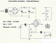
I don't think one could find a more vanilla 0 dB buffer, than this.
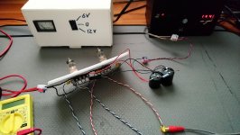
You don't even need a 'case' for it, to try.
Just use alligator-clips on the bend.
And set up the power supply bit on a tiny breadboard.
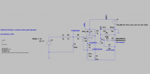
Don't forget that the 10 kΩ resistor in the power supply is going to get hot. Use a 5 watt part, or a string of lower-watt, lower-Ω parts to make the 10 kΩ.
⋅-=≡ GoatGuy ✓ ≡=-⋅
Nothing is going to break, or be bad.
I don't think one could find a more vanilla 0 dB buffer, than this.
You don't even need a 'case' for it, to try.
Just use alligator-clips on the bend.
And set up the power supply bit on a tiny breadboard.
Don't forget that the 10 kΩ resistor in the power supply is going to get hot. Use a 5 watt part, or a string of lower-watt, lower-Ω parts to make the 10 kΩ.
⋅-=≡ GoatGuy ✓ ≡=-⋅
One thing i do not understand, that schematics claims there should be negative 1.9 volts on the grid. Negative. Where does one generate negative volts? Its only powered by asymetrical power supply. I measure above fifty volts on the grid, positive off course.
Why do they expect grid to get negative? Towards what reference? I measure only agaist the ground.
Why do they expect grid to get negative? Towards what reference? I measure only agaist the ground.
Member
Joined 2009
Paid Member
Member
Joined 2009
Paid Member
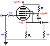
in the schematic you started with, the second grid is connected to the anode which is a fairly traditional way to turn a pentode into a triode, by feeding back the signal from the anode to the second grid
however when you are using it as a cathode follower the signal is now on the cathode and if you want to use this in Triode mode you need a way to feedback the signal from the cathode to the second grid - I have attached an example from Broskie of how to do it
however when you are using it as a cathode follower the signal is now on the cathode and if you want to use this in Triode mode you need a way to feedback the signal from the cathode to the second grid - I have attached an example from Broskie of how to do it
Attachments
- Status
- This old topic is closed. If you want to reopen this topic, contact a moderator using the "Report Post" button.
- Home
- Amplifiers
- Tubes / Valves
- 6J1 buffer/preamp