I've confirmed that the voltages are good and there are no shorts or obvious wiring faults. During this test, there was a moderate amount of buzz and hum and my 8 ohm dummy load got very hot. I disconnected it and left it as I didn't have all of the test gear on hand and it was late.
I've rerun the test this morning with a scope across the output and this is what I got. 39Hz square wave at 47V p-p.
This has been built to a different layout which I feel may be a contributory factor but otherwise, I've made no other modifications.
I'm a little baffled as to the likely cause.
I've rerun the test this morning with a scope across the output and this is what I got. 39Hz square wave at 47V p-p.
An externally hosted image should be here but it was not working when we last tested it.
This has been built to a different layout which I feel may be a contributory factor but otherwise, I've made no other modifications.
I'm a little baffled as to the likely cause.
Thank you both for that. Disconnecting the feedback was on my list of things to try. Just done it and that did the trick. No signal of any consequence out with no input. Testing with the signal generator connected and a simple 1KHz sine input.
It's a bit odd as I asked which side of the secondary I take the negative feedback from. The answer came back as the 8 ohm tap rather than the common.
An externally hosted image should be here but it was not working when we last tested it.
It's a bit odd as I asked which side of the secondary I take the negative feedback from. The answer came back as the 8 ohm tap rather than the common.
Last edited:
It's a bit odd as I asked which side of the secondary I take the negative feedback from. The answer came back as the 8 ohm tap rather than the common.
The polarity can be inverted at the primary side too - either swap the grid drives over or swap over the Anode/UL connections between the output valves (both will work but one will likely lead to less re-work / annoyance, don't do both of course!)
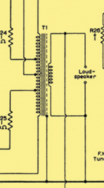
This is the wiring diagram for the sowter output transformers that I used.
I've got green and yellow going to V4 and grey/brown going to V3 which I think is likely where the error is.
An externally hosted image should be here but it was not working when we last tested it.
I've got green and yellow going to V4 and grey/brown going to V3 which I think is likely where the error is.
An externally hosted image should be here but it was not working when we last tested it.
It is always 50/50 chance of getting a new build push pull amp into positive rather than negative feedback... You did the right thing using a dummy load rather than speakers!!!
Put the common (red) output back to ground, use the 8 ohm tap for feedback. Then swap the green and yellow wires with the grey and brown pair.
Alan
Put the common (red) output back to ground, use the 8 ohm tap for feedback. Then swap the green and yellow wires with the grey and brown pair.
Alan
This is the wiring diagram for the sowter output transformers that I used.
Without phasing dots in the transformer diagram you cannot assume any particular phase relationships between separate windings.
(And even then I'd check!)
And it's now sorted with negative feedback connected. I've swapped the anode/UL connections between the two output valves. Tested it with a dummy load for a while getting a load of measurements and checking waveforms.
Voltages - I think some of the higher voltage readings are down to my fluke 28 having a different resistance to the Avometer used for the numbers in the book.
1KHz square wave input shows some ringing. HF instability or normal?
10KHz square wave input also shows more ringing Sine looked clean out to 50KHz.
Testing with audio and one of my old DIY Kef based speakers. Sounds good and the best news is that it is completely silent, with minimal hiss audible at the tweeter and no hum.
Voltages - I think some of the higher voltage readings are down to my fluke 28 having a different resistance to the Avometer used for the numbers in the book.
An externally hosted image should be here but it was not working when we last tested it.
1KHz square wave input shows some ringing. HF instability or normal?
An externally hosted image should be here but it was not working when we last tested it.
10KHz square wave input also shows more ringing Sine looked clean out to 50KHz.
An externally hosted image should be here but it was not working when we last tested it.
Testing with audio and one of my old DIY Kef based speakers. Sounds good and the best news is that it is completely silent, with minimal hiss audible at the tweeter and no hum.
An externally hosted image should be here but it was not working when we last tested it.
In principal, the ringing doesn't bother me. I was just intrigued to know if it was normal and ok at the level that it is at here.You can mess with the value of C8 if square wave ringing is something that bothers you.
Currently the feedback network values I've got are 330pF for C8 and R15 is 5.62K.
Are the slight signs of the plates glowing at the edges anything to worry about? The camera sees it better than I do. To me in a dark room, it is barely visible.


R20 & R21 are 470ohm 5W resistors that measured ok. Playback sounds great. I'm assuming it's my inexperience with valves that is making me check.
R20 & R21 are 470ohm 5W resistors that measured ok. Playback sounds great. I'm assuming it's my inexperience with valves that is making me check.
FWIW, I see glowing cathodes, not red spots on the tube plates. "Red plating" is bad, as excessive current is flowing inside the device.
Your comfort level can be improved by increasing the negative bias voltage applied to the O/P tubes' control grids, at "idle". That decreases the "idle" current.
Your comfort level can be improved by increasing the negative bias voltage applied to the O/P tubes' control grids, at "idle". That decreases the "idle" current.
Last edited:
I do see some red-plating in the photos! Eli, look at the two EL34’s plate structures, middle of the right flange on both tubes in the first shot.
Cameras are reportedly more sensitive to infrared than the human eye; perhaps that is what we see in the photos. If you can not see it with the naked eye in a dark room it should be ok, else I would adjust down the bias current.
Edit. I just looked at your measured voltages and bias current (I think your meter is probably correct and your voltages are actually higher than intended in the design). At idle it appears that you have just under 430 v across the EL34s with 68 ma current. That is close to 30 watts! Too high for a 25 watt tube. It appears that the design ran the tubes at maximum dissipation and you B+ is higher than the design original. Perhaps you can consider bringing down your B+ (bucking transformer, viariac, etc). I’m puzzled by the fact that your heater voltage is so low.
Last edited:
The heater voltage is low as I’m running the HT transformer primary on it’s 250V tap and my mains voltage is normally 237V. The HT voltage should be 410V before the rectifier which I’m fairly sure it was within 5V of when I checked it with no load. I guess the mains voltage last night may have been higher than usual.
The transformer and choke both felt a fair bit hotter than they did during my testing the day before but I think the ambient temperature was higher last night and there was less air flow as the windows were closed.
What is a little strange is that the slight glow on the plate was only on the one side. There was no symmetrical signs on the opposite welded side. It is barely visible to the eye, you need to be up very close to see anything. 2 feet or more away and it’s simply not possible to see it. It certainly doesn’t look severe.
R20 & R21 are 470ohm 5W resistors that measured ok. Playback sounds great. I'm assuming it's my inexperience with valves that is making me check.
You mean R17 / R18 which are the cathode resistors?
The valves do look a bit hot to me - normally even with a long exposure shot you shouldn't be able to see any red on the plates (on a camera with decent IR rejection)....
Yes the cathode resistors. The component numbering keeps varying depending on the diagram I look at. I'm using the mullard book numbering.You mean R17 / R18 which are the cathode resistors?
The valves do look a bit hot to me - normally even with a long exposure shot you shouldn't be able to see any red on the plates (on a camera with decent IR rejection)....
I've run it all morning with the other set of valves and detected no signs of glowing plates, but the temperature in my room today is down to 22 degrees where it was around 27 yesterday.
I've double checked the HT from the transformer with no load and it is 406Vac before the rectifier which in principal is worst case scenario, so if anything, all voltages should be slightly lower than the book values.
Attachments
I've double checked the HT from the transformer with no load and it is 406Vac before the rectifier which in principal is worst case scenario, so if anything, all voltages should be slightly lower than the book values.
But they are not! Or are they now? In post #9 you showed a high voltage supply that is almost 20V higher than designed. And as designed it appears that the EL34s were running at maximum dissipation.
A simple way, providing the 5 VAC winding on the power transformer is good for 3 A., to slightly lower the B+ rail voltage is swapping the 5AR4/GZ34 out and installing a 5U4GB. Forward drop in a 5U4 is somewhat greater than that in a 5AR4.
Directly heated types, like the 5U4, turn on nearly as fast as SS diodes do. To "soften" B+ rail rise and protect against power turn on arcing, install a CL-140 inrush current limiting thermistor between pin 8 of the rectifier socket and the 1st filter capacitor. Construction with a cathode sleeve makes the 5AR4 start slowly and the type is unusually tolerant of a "large" 1st filter capacitor. Installing a CL-140 increases the comfort zone, when replacing a 5AR4 with a 5UBGB.
Directly heated types, like the 5U4, turn on nearly as fast as SS diodes do. To "soften" B+ rail rise and protect against power turn on arcing, install a CL-140 inrush current limiting thermistor between pin 8 of the rectifier socket and the 1st filter capacitor. Construction with a cathode sleeve makes the 5AR4 start slowly and the type is unusually tolerant of a "large" 1st filter capacitor. Installing a CL-140 increases the comfort zone, when replacing a 5AR4 with a 5UBGB.
The numbers I'm seeing don't seem to add up. That voltage I measured today is the HT AC voltage directly at the point where the transformer connects to the rectifier socket. (one side to ground) According to the mullard spec, this should be 410Vac going in. I'm seeing 406Vac. Once rectified, I can't see how I can get higher than their book figures if I have a lower voltage going in.But they are not! Or are they now? In post #9 you showed a high voltage supply that is almost 20V higher than designed. And as designed it appears that the EL34s were running at maximum dissipation.
I'd prefer to avoid making significant modifications to the design if I can. I assume the SS diode mod used to prevent arc over in the 5AR4 wouldn't be able to cause the increased rectified voltages i'm seeing.A simple way, providing the 5 VAC winding on the power transformer is good for 3 A., to slightly lower the B+ rail voltage is swapping the 5AR4/GZ34 out and installing a 5U4GB. Forward drop in a 5U4 is somewhat greater than that in a 5AR4.
Directly heated types, like the 5U4, turn on nearly as fast as SS diodes do. To "soften" B+ rail rise and protect against power turn on arcing, install a CL-140 inrush current limiting thermistor between pin 8 of the rectifier socket and the 1st filter capacitor. Construction with a cathode sleeve makes the 5AR4 start slowly and the type is unusually tolerant of a "large" 1st filter capacitor. Installing a CL-140 increases the comfort zone, when replacing a 5AR4 with a 5UBGB.
Last edited:
- Home
- Amplifiers
- Tubes / Valves
- Testing newly built mullard 5-20