Hi,
does somebody have a good 211 / VT4C schematic like Air Tight ATM-211 to recommend ? If it's possible without interstage transformer and 6SN7 input valve.
I have some, but I would like to have opinion those which used these valve and to share their experiment
Thanks.
Pascal.
does somebody have a good 211 / VT4C schematic like Air Tight ATM-211 to recommend ? If it's possible without interstage transformer and 6SN7 input valve.
I have some, but I would like to have opinion those which used these valve and to share their experiment
Thanks.
Pascal.
Simple 211
About the least complex 211 I've seen is the design on PAE's site:
PAE 6C45 --> 211 amplifier
I built a version (with a very different power supply design) with a more modest B+ (825vdc) that I've been enjoying.
Use RF precautions around the 6C45 (grid stoppers, RF beads).
- Gary
My website....
About the least complex 211 I've seen is the design on PAE's site:
PAE 6C45 --> 211 amplifier
I built a version (with a very different power supply design) with a more modest B+ (825vdc) that I've been enjoying.
An externally hosted image should be here but it was not working when we last tested it.
Use RF precautions around the 6C45 (grid stoppers, RF beads).
- Gary
My website....
Has anyone built this amp? I'm quite curious about it... I like it's simplicity:
http://digilander.libero.it/paeng/6c45_211_documentation_page.htm
@ Gary / The-Planet : What is your version of the power supply??
Thanks
About the least complex 211 I've seen is the design on PAE's site:
http://digilander.libero.it/paeng/6c45_211_documentation_page.htm
@ Gary / The-Planet : What is your version of the power supply??
Thanks
211: µ≈11
845: µ≈5
GM70: µ≈6
Is that the right schematic ?
http://www.triodedick.com/goliath/goliath_versterker.GIF
Than you can't use it. The 27/56 doesn't have the ability to drive the low-µ GM70.
Rough calc: Ub≈1000V -> GM70 has to control 2000V with a mu of 6 -> you have to deliver a Vpp of 2000/6 ≈ 333Vpp
Vpp from the driver in the schematic is too low.
Hi!
The D3A is a poor choice as a driver IMHO, way too little headroom. While the possibility to get away with 2 stages might be tempting, over simplyfing things can be a bad compromise. Yet it can be done with 2 stages
Here is my approach to a 2-stage 211 amp, not very simple, but good")
VinylSavor: Making of a 211 Amplifier, Part 1: Planning
Thomas
The D3A is a poor choice as a driver IMHO, way too little headroom. While the possibility to get away with 2 stages might be tempting, over simplyfing things can be a bad compromise. Yet it can be done with 2 stages
Here is my approach to a 2-stage 211 amp, not very simple, but good
VinylSavor: Making of a 211 Amplifier, Part 1: Planning
Thomas
Hi
Thank you very much.
I see U use inter stage transformer. I would like to avoid to use one.
There are many design with 2 stage with out inter stage transformer. Some people say the D3a would be the best choice.
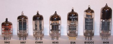
Many of these tubes have a plate resistance
about 2Kohm but only the D3A and 6C45
have an amplification factor greater than 50
D3A specifications in triode connection:
filament voltage: 6.3V
filament current: 315mA
Max plate voltage: 200v
Max plate dissipation: 4.2w
Max cathode current: 33mA
Plate resistance: 1.9Kohm
Amplification factor: : 77
Max resistance in grid circuit: 0.5Mohm
6C45 specifications:
filament voltage: 6.3V
filament current: 440mA
Max plate voltage: 150v <<<<< it is lower than D3a
Max plate dissipation: 7.8w
Max cathode current: 52mA
Plate resistance: 1.2Kohm
Amplification factor: 52 ±16 <<<<< selection is necessary
Max resistance in grid circuit: 0.15Mohm
Inter electrode capacitance:
input: 11±2 pF
output: 1.9±0.3 pF
transfer: 4.5pF
Greetings
Thank you very much.
I see U use inter stage transformer. I would like to avoid to use one.
There are many design with 2 stage with out inter stage transformer. Some people say the D3a would be the best choice.
Many of these tubes have a plate resistance
about 2Kohm but only the D3A and 6C45
have an amplification factor greater than 50
D3A specifications in triode connection:
filament voltage: 6.3V
filament current: 315mA
Max plate voltage: 200v
Max plate dissipation: 4.2w
Max cathode current: 33mA
Plate resistance: 1.9Kohm
Amplification factor: : 77
Max resistance in grid circuit: 0.5Mohm
6C45 specifications:
filament voltage: 6.3V
filament current: 440mA
Max plate voltage: 150v <<<<< it is lower than D3a
Max plate dissipation: 7.8w
Max cathode current: 52mA
Plate resistance: 1.2Kohm
Amplification factor: 52 ±16 <<<<< selection is necessary
Max resistance in grid circuit: 0.15Mohm
Inter electrode capacitance:
input: 11±2 pF
output: 1.9±0.3 pF
transfer: 4.5pF
Greetings
Attachments
Hi!
Well I wrote that it is in my opinion a poor choice. Depends on which compromise you want to make. What the D3A and all the other tubes which you mentioned lack is headroom.
While the D3A would be the better choice I still prefer more headroom.
It's all about the choice you make. Sure it will work, might even suit your taste.
The D3A is a great tube, just not for this application IMHO
Thomas
The circuit in the goliath is a so called µ-follower. Short version: The 27/56 "makes" the sound and the D3A's purpose is to give 27/56 a good environment considering output resistance and loadline.
Driving a 845/GM70 isn't as easy as driving a 6L6. I don't want this to get too long, but to sum it up: The Signal Voltage to drive the 845 is very high, as calculated above. The 845 is in A1 operation which means we don't have to deal with positive grid voltage and grid current, but it has a large Grid-Anode capacity. Furthermore an ugly thing called Miller Effect multiplies this capacity by (µ+1)≈7. So the driver still has to deliver some current to charge that capacity each half cycle.
How to deal with that in practice ?
There are two and one stage designs. Two stage design uses a standard small signal tube at first. The second stage doesn't have to amplify very much, but must be able to swing large signals and deliver some current. 300B, EL34, 6L6 is often used here. Some designs avoid to use large tubes in the second stage and use SRPP. Using two small signal tubes on top of the other, you can give them double times their max. anode voltage. interestingly the SRPP principle has been used exactly for that purpose - delivering high voltage amplitudes to fixed loads. Problem is that the 845 isn't a constant load, since the resistance is depending on the frequency. That's the flaw with that design.
Single stage designs must obviously use high-µ valves. Moreover they must also be able to swing large volatges. Many high-µ pentodes (or triodes/pseudotriodes) have a max-Ua of only 200V. There are a few exceptions like the EL802 which can withstand 300V. Yves built an amplifier with it: Preliminary 845 SET
Another option is to use High-voltage-TV-switch-shunt-triodes. They have enormous high µ and gm. These aren't sweep tubes nor high voltage shunt regulation tubes. It's a kind of hybrid but very well suited as a driver. They require at least the Ub of the 845/GM70 ! Just look at Thoma's amplifier.
Hello
I just retract my bid at the Ebay on the D3a tube! Thank you very much for the warning.
Al do I have several schematic based on two stage design!
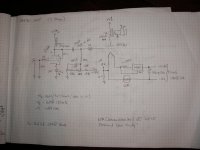
Here is one design by Andrea Ciuffoli
845 Amplifier with only two stages
Only problem the 100H choke have to be special low resistance.
I attach other two stage design at the next post, but I'll go with 3 stage now!
For these circuit 6SN7 & 6J5 I ordered the tubes and sockets.
I try to build these, all do these need at least 3 or 4 power transformer
I will attach at the next post some 2 stage working design!
Thanks one more time
Greetings gabor
I just retract my bid at the Ebay on the D3a tube! Thank you very much for the warning.
Al do I have several schematic based on two stage design!
Here is one design by Andrea Ciuffoli
845 Amplifier with only two stages
Only problem the 100H choke have to be special low resistance.
I attach other two stage design at the next post, but I'll go with 3 stage now!
For these circuit 6SN7 & 6J5 I ordered the tubes and sockets.
I try to build these, all do these need at least 3 or 4 power transformer
I will attach at the next post some 2 stage working design!
Thanks one more time
Greetings gabor
Attachments
Last edited:
Hello
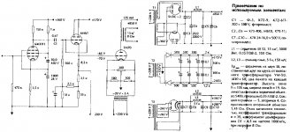
Here are some 2 stage design
The third schematic here!
http://www.goodsoundclub.com/pdf/6E5P_Swedish.pdf
One of the derived by D3A tube at the attachment.
These is another design
Nicholas' GM70 SE Amp There are more schematic but I do not want to dump all those here....
Any way I try first the 3 stage with 6SN7 & 6J5 tubes. Only problem I have with that design the low plate voltage.
I would like to go with 900V on the plate and a bit less bias.
In case if these design does not work out for me I do not want to buy another power transformer.
Greetings gabor
Attachments
211 single ended power amp circuit and parts list
I would love The Schematic Circuit of The 211 With The Input Tube and The Driver Tube, Could you please send a Copy to me My: e mail is: fsj@iprimus.com.au
Rgds
Francis Jansz
Dear Gaborbela,Hello
Can someone let me know if I can replace the 211 tube with GM70 type?
I know I can replace 845 with GM70 if I adjust the heater voltage. GM70 use 20V for filament.
I have a nice 211 schematic "Goliath" but I want to use GM70 power tubes.
Greetings gabor
I would love The Schematic Circuit of The 211 With The Input Tube and The Driver Tube, Could you please send a Copy to me My: e mail is: fsj@iprimus.com.au
Rgds
Francis Jansz
Has anyone built the 211 version on the PAE website with the 6C45-211 schematic?
The Documentation Page for the 6C45/211 Single Ended Amplifier
How does it sound?
The Documentation Page for the 6C45/211 Single Ended Amplifier
How does it sound?
- Home
- Amplifiers
- Tubes / Valves
- 211 VT-4C Good Simple SE Schematic