Hello All,
Thanks to all of the useful help from this forum earlier, I was able to resolve all of the issues with my tube amp. I got some new EL34's and rewired the preamp socket to run a 12AX7 and it sounds amazing. Pure SE bliss.
Here are the previous threads I posted:
https://www.diyaudio.com/forums/tubes-valves/351067-help-6n2-el34-tube-amp-kit.html
https://www.diyaudio.com/forums/tubes-valves/351256-regulating-filament-voltages.html
All of the issues in the previous threads were solved. My filament and bias voltages and currents for the tubes were all within range.
In designing an enclosure, I did run into a few questions I had and figured you folk would be the best to consult with.
1) Extending the Tube Sockets
2) Improving the Bass Response
3) Powering the VU meters with the filament taps on the power transformer.
I did a little research on all of the topics, and these were the recommendations I found.
1) In extending the tube sockets, if I read correctly, the grid stopper resistors need to be close to the tubes to work effectively. Would it be a better idea to run a jumper on the PCB and solder the grid stoppers between the tube base (that will plug into the PCB) and the panel mount socket? I also saw a thread where a 100 ohm resistor was soldered in line with the grid extension, leaving the grid stopper in its initial location.
2) In expanding the bass response, I have read that the OPT and coupling capacitors are the main factors in determining the bass response. My coupling capacitors from the 12AX7 to the EL34's are 0.47uF currently. I was looking at replacing the OPTs with two of these:EDCOR - XSE10-5K, but I would like to see if there's anything else I can do before ordering a pair.
3) I was looking at adding a voltage doubler circuit through the filament supply to power the control board for my VU meters. Would this introduce any noise/distortion to the heaters? I read that there is a possibility of frying the diodes if the DC side of the circuit is connected to ground, but my 6.3V does not have a center tap, so would it pose an issue?
Attachments
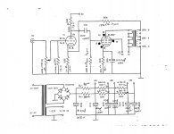
EL34 is a Pentode.
EL34, connect the suppressor grid and cathode together. Pin 1 to Pin 8.
Do not let pin 1 float.
Beam Power tubes like 6L6, KT66, KT77, and KT88 already have a connection inside the tube from the Beam Formers to the Cathode.
For a true EL34 tube diagram:
The suppressor grid is nearest to the plate.
The control grid is nearest to the cathode.
The screen grid is between the control grid, and the suppressor grid.
That is not how you connected them on your schematic (the physical position of the grids).
Someone might build that amp too, and make improper connections.
All grid stopper resistors should have one end connected directly to the tab of the tube socket. To do anything else will defeat the action and purpose of the grid stopper.
The 0.47uF and 470K grid resistor has a time constant of 0.22 seconds, and 5 time constants of 1.1 second. If you turn the volume high enough to draw grid current, it will take a very long time to recover.
0.47uF and 470k has a -3dB low frequency point of 0.72 Hz, and has a -1 dB low frequency point of 1.44Hz. The phase shift at 0.72 Hz is 45 degrees, and 26 degrees at 1.44Hz.
Having that low of a phase shift should prevent negative feedback problems. Well except the following:
If you actually have a signal at that low of a frequency (like 3 Hz from a warp on a vinyl record), the transformer will saturate. And negative feedback does not like transformer saturation.
You will not want to purchase an output transformer that will respond to frequencies that are that low ($$$).
What manufacturer and model output transformer do you have?
The 6.3V secondary should have a Pseudo center tap, two 100 Ohm resistors in series, the resistor ends on the secondary ends, and the middle of the series resistors connected to ground. (and remove that ground from one end of the 6.3V secondary). That will give the best noise and hum that could come from the filaments.
Then, since we do not know anything about the VU meters, you most likely need another transformer to power them. They most likely are not floating (and the signal has to connect across the output transformer secondary), right?
And one end of the output secondary has to be connected to ground to make the negative feedback work.
Do use a separate power supply for the vu meters.
Last edited:
Thanks for the response. The amp was built from a kit with a supplied PCB. The connections on the board are correct, even though the schematic has the wrong grids labeled. I can solder a little jumper to attach the suppressor grid to the cathode. I have a virtual center tap with two 100 ohm resistors, but the amp's self noise is incredibly low even without it connected.
As for extending the tube sockets (2" max length), all I'll need to do is move the grid stoppers to the bottom of the flush mount socket and replace the PCB position with a jumper. Sounds good.
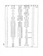
The included output transformers do not have a brand, however the included parts list specifies that they are 5.2k ohm with 4/8 ohm taps on the secondary side. Would joining the cathode and suppressor grid improve bass response?
I was asking about powering the VU board from the filament supply only because the enclosure I have the amp in currently has limited space. Placing another power transformer would situate it very close to the OPTs, but I do have a compatible transformer. I'll probably build a proper case for this so this isn't a big deal.
As for extending the tube sockets (2" max length), all I'll need to do is move the grid stoppers to the bottom of the flush mount socket and replace the PCB position with a jumper. Sounds good.
The included output transformers do not have a brand, however the included parts list specifies that they are 5.2k ohm with 4/8 ohm taps on the secondary side. Would joining the cathode and suppressor grid improve bass response?
I was asking about powering the VU board from the filament supply only because the enclosure I have the amp in currently has limited space. Placing another power transformer would situate it very close to the OPTs, but I do have a compatible transformer. I'll probably build a proper case for this so this isn't a big deal.
Regarding extending tube sockets and grid stoppers, I recently made some socket adaptors so I could use some loctal tubes in place of KT66’s. I was concerned about the grid stopper, so in the end I added a ferrite bead at the tube pin on the loctal socket. Does anyone envisage an issue with that?
OldHector,
A resistor grid stopper has the following characteristics:
Series resistance. And, the following parasitics:
Series inductance (think of the inductive reactance increasing at very high frequencies)
Parallel capacitance (think of the capacitive reactance decreasing at very high frequencies).
The effectiveness of the grid stopper is dependent on the resistor ohmic value, and the above listed parasitics over a range of very high frequencies.
A ferrite bead with a wire through it. The effectiveness as a grid stopper also varies over a range of frequencies.
Not a definitive answer, but does that help?
jsmith2217,
1. The operation of an EL34 that has the suppressor grid floating (not connected) is not defined. It always should be connected to something. (only in special cases is it connected to anything other than the cathode; many Power Pentodes already make that connection inside the tube . . . you do not have the choice, and most generally, no choice is a good thing).
In most cases, it should be connected to the cathode, including your amp.
First, make sure that a hidden trace on one side of your circuit board is not already connecting it somewhere.
Joining the suppressor grid to the cathode may or may not change the bass response, but always have it connected.
2. You say that with only the two 100 Ohm resistors connected to ground (and neither of the the 6.3V secondary wires grounded?) that you do not get hum and noise. That is good.
But if later, you use another input tube that has filament to cathode leakage, you likely will get hum and noise.
So, you either need to use the two 100 Ohm resistors to ground (Pseudo center tap), that is best.
Or, the next best is with no resistors, and one end of the 6.3V secondary connected to ground.
The problem with either of these hum and noise reduction connections, is that you can not use a voltage doubler to power your VU meters from the 6.3V secondary that is grounded either with the resistors, or the direct connection of one end to ground.
If you float the 6.3V, no ground connection, and then use a voltage doubler to power the VU meters, the negative output from the voltage doubler needs to be grounded.
That circuit may put hum and noise back on the input tube cathode (only building and testing that will tell you if it is a problem or not).
2 - 1/2. That is because your VU meters have 3 wires: Ground (common for power and for signal); + Power; and Signal.
True?
False?
A possible way to power you VU meters depends on how much current they draw, and on what voltage they need to power them.
Depending on that, you might be able to use a resistive divider from B+ to power the VU meters.
What are the power requirements of the VU meters - voltage and current?
kokoriantz,
Reducing the resistance of the EL34 cathode resistor will do several things:
1. Make the EL34 run hotter
2. Make the power transformer run hotter
3. Put more DC current in the output transformer, making it saturate earlier, especially on Bass notes.
4. This amplifier has negative feedback that comes from the output transformer secondary. If the transformer core saturates, the negative feedback will apply a correction signal that will drive even more current into the transformer, making it saturate even more. That is a loosing battle.
The EL34 in this amp is wired in Pentode mode.
An EL34 that is Triode wired, and if the current is increased, the rp will reduce, and that will make for better bass.
But triode wired has less power out. That is a tradeoff.
The power transformer and output transformer are designed to work at the power and current levels they are working at now. This is not an expensive high end amplifier (and some expensive high end amplifiers are at their limits too).
Just my opinion.
Other than the 4 items above, it might work OK.
Last edited:
kokoriantz,
Reducing the resistance of the EL34 cathode resistor will do several things:
R106 is for the negative feedback.
Could R106 be bypassed as well?
kokoriantz,
Sorry, I misread the schematic.
The EL34 cathode resistor marking was not clear on my screen, I thought it said R106;
No it is R105.
Decreasing the resistance of R106, the feedback resistor will do 3 things:
1. Reduce the amplifier gain.
2. May reduce the amplifier stability, it may oscillate, especially depending on the speaker that you use (and the output transformer that you use).
3. It may make the Bass stronger at low and mid power levels, but only until the transformer saturates.
Once the transformer saturates, the negative feedback will cause it to saturate even more.
High level Bass will distort more, not less.
And if the resistance of R106 is decreased, OldHector was right, you may need a capacitor across R106.
The value will depend on what output transformer you use, and could also change depending on what loudspeaker you use.
The problem is that normally you need a scope and square wave generator to be able to see the resultant output, so that you can adjust that added capacitor value to make the amp stable.
One small change often requires 3 more changes in order to make things work.
Last edited:
6A3sUMMER,
Thank you for all of the helpful advice. I am not too worried about powering the VU meters. I just got some materials to build an actual case for the amplifier, so space won't be a problem to incorporate another small 12VAC transformer in there.
I tied Pins 1 and 8 together on the EL34's (they were not connected in any way by the PCB) but the amp still sounds a little high. Sound quality is phenomenal, as is such from a SE amp and the self noise is even lower after adding the pseudo center tap but it is still lacking a little power on the low end.
I connected my phone to it and used a software equalizer to see if I could stretch out a little more bass before the OPTs saturated and it was able to produce a decent amount before saturating. When this amp is finished, I plan on having it attached to my turntable and cassette deck, so there aren't really any EQ controls there.
Would it be feasible to add some sort of tone control?
Weigh one of the output transformers that you have.
Check online the specified Net weight of the Edcore XSE 10-5.
Does that answer your question about which is more likely to respond better to loud bass, and to very low frequency bass notes?
Do not worry about the different impedances of a 5k transformer versus a 5.2k transformer.
Your loudspeaker impedance may vary by as much as 10:1 or more, across the audio band (20Hz to 20kHz).
Even if your loudspeaker only varies by 3:1, that makes the 5k vary by 3:1, hopefully centered around 5k.
Last edited:
XSE 10-5 1.2 lbs. $19
XSE 15-5 1.6 lbs. $22
GXSE 10-5 1.75 lbs. $38
GXSE 15-5 2.75 lbs. $42
Hammond T125DSE 2.33 lbs. $46
All things being fairly equal, Bass response of SE transformers is related to weight.
All things being fairly equal, Laminations, and enough copper wire around the laminations is related to the price of an SE transformer.
Part of the problem is the picture that shows the output transformers on the circuit board.
More laminations and more copper not only is more expensive, it takes up more space.
- Status
- This old topic is closed. If you want to reopen this topic, contact a moderator using the "Report Post" button.
- Home
- Amplifiers
- Tubes / Valves
- EL34 Tube Amp Modification Advice