Hi Mark,
Ok, so they are not the same circuits. Given the circuit below, can it provide two positive voltages? If so, how? And if it can, what size voltage caps should I have on it: the total voltage on the circuit? or can they be split to add up to the total voltage? Thanks.
No, please ignore that circuit. See post #11 and post #14.
Or will it only provide one positive voltage?
And the value of the caps for post #11 circuit:
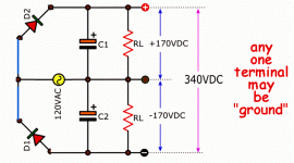
Your circuit is grounded at the center output node, so it gives one positive voltage and one negative voltage
with respect to ground (the center terminal). This is because the other two diodes have their anodes
connected to the bottom terminal of the three output nodes, and can only produce a negative voltage.
This polarity connection of the bridge rectifier is necessary since there is no center tap on the secondary.
This means that you could not reverse those two diodes to give a positive voltage, the circuit would not work.
In post #11, normally the two capacitors should be identical.
Last edited:
This is the FWB circuit. The lower output is grounded.
How is there any current flow out of node V2?
Mike
Ok, got it. Now I understand about the neg and positive voltages.
As for the caps: If the total voltage requires 1000v then the two caps can be rated at 500v each, correct?
We always want to derate components due to many factors. It would be very risky to run a 500V capacitor right at 500V. The two capacitor voltages will not balance perfectly even with equal resistor bleeders across each. The line voltage may rise significantly at times. The transformer secondary voltage may be higher than expected due to manufacturing tolerance
or light loading. The two output nodes will have different amounts of current drawn from them.
I normally derate electrolytic capacitors by at least 20% in voltage, often more.
Last edited:
How is there any current flow out of node V2?
Mike
The V/2 node (meaning one half of V, the top node) is for the powering the low current driver or input circuit.
It is half the voltage of the top node (which is labeled V).
Last edited:
The V/2 node (meaning one half of V, the top node) is for the powering the low current driver or input circuit.
It is half the voltage of the top node (which is labeled V).
You didn't answer my question...regarding the diagram in post #11, how do you get DC current flow through a capacitor?
Mike
Erm, B+ is positive. How can a negative voltage possibly provide B+?
Your circuit is grounded at the center output node, so it gives one positive voltage and one negative voltage
with respect to ground (the center terminal). This is because the other two diodes have their anodes
connected to the bottom terminal of the three output nodes, and can only produce a negative voltage.
This polarity connection of the bridge rectifier is necessary since there is no center tap on the secondary.
This means that you could not reverse those two diodes to give a positive voltage, the circuit would not work.
Ok, I understand what you re saying that this circuit gives two voltages. But it would seem that it gives three in fact: one +170v, one -170v and one +340v. Where/ how does it it get the third (total) voltage?
You can ground the center, and then you would get +170, and -170, or you can ground the bottom, and you would get +340 and +170.
Why don't you just say what the application is? Do you want a lower positive voltage for an input stage, or for a screen grid? Do you want a negative voltage to DC couple the driver stage to output stage? You will get better answers.
Why don't you just say what the application is? Do you want a lower positive voltage for an input stage, or for a screen grid? Do you want a negative voltage to DC couple the driver stage to output stage? You will get better answers.
You can ground the center, and then you would get +170, and -170, or you can ground the bottom, and you would get +340 and +170.
Why don't you just say what the application is? Do you want a lower positive voltage for an input stage, or for a screen grid? Do you want a negative voltage to DC couple the driver stage to output stage? You will get better answers.
I want two positive voltages to drive the b+ of two tubes with one rectifier.
I want two positive voltages to drive the b+ of two tubes with one rectifier.
Again, not enough detail. Are you just driving a simple 2 stage amp? Better to forget voltage doubling, and just use an RC filter to derive the B+ for the input stage.
simple 2 stage amp HV rectifier need for B+ of v2; v1 needs half voltage.
I would like to derive the voltage for both tubes from one p/s. Can it be done?
See post #11. I'll be bowing out now.
sorry, there was more detail at the beginning of this thread. Maybe not enough.
Yes, simple 2 stage amp HV rectifier need for B+ of v2; v1 needs half voltage. I would like to derive the voltage for both tubes from one p/s. Can it be done?
A high voltage winding with a center tap bridge rectified with the negative output of the bridge grounded will give you an output that's half the B+ on the center tap of the HV winding.
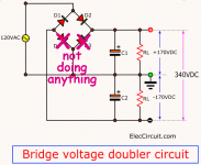
please find attached the image of the v. doubler circuit.
That's wasteful. It does NOT need a 4-diode bridge. It is clear on inspection that D3 D4 do not do anything.
It works as the 2-diode form in the second picture. "Ground" is arbitrary.
Post less. Think more.
Attachments
- Status
- This old topic is closed. If you want to reopen this topic, contact a moderator using the "Report Post" button.
- Home
- Amplifiers
- Tubes / Valves
- filtering neg leg of a bridge rectifier

