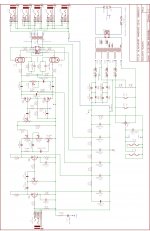
given the schematic added, regarding the V1 conversion of a parallel triode gain stage into the c8 (coupling cap/ LTPI input)
due to parallel triodes behaviour, the following resistors/capacitors in the LTPI network must be changed to be seen/operate at same values as default by design:
c8: 22nf (10nf) [or 2 22nf in series]
r12: 1m (470k) [or 2 1m parallel)
r11: 47k (22k) [2x 47k parallel]
r13: 1.5k (820r) [2x 1.5k parallel]
r14: 1m (470k) [2x 1m parallel]
c9: 100nf (50nf)
is it right?
Attachments
Last edited:
Can't read your schematic, not enough detail.
Need more resolution.
Is this another guitar amplifier?
It seems like all the tube science is in the Hi Fi part of the DIY forum.
I am not sure, because I do not visit the 'Instruments and Amps' part of the DIY forum.
What parallel triodes?
An LTP (Long Tailed Pair) is not parallel triodes, the triodes are in anti-phase mode.
With a resistor used as a "current sink" for the paralleled cathodes, the plate loads have to be different resistances, or the in-phase and out-of-phase signals will not be equal amplitude.
You would have to use a true current sink, not a resistor, in order to get the amplitudes equal when the plate loads are equal.
Last edited:
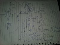
i'll draw on paper the schem later then, but basically the thing is:
the signal feeding the ltpi comes from a plate-driven gain stage, this stage is a paralleled 12ax7
since i know the paralleled plates resistor and coupling cap behave in a different way (the plate resistor must be halved and the coupling cap too)
i aint sure if the same happens when the signal from the parallel plates reach the ltpi network since they are coupled and i havent halved their values yet
edit: new scheme added
Attachments
Last edited:
You skipped over my main question:
Is this for a Guitar Amplifier?
Thanks!
it seems to get lost on skips due to the fact that my main question was skipped aswell so i should apologize for skipping the skippy-skip, but oh well... its a tube amplifier
if you examine carefully the design of the original scheme (on zoom you can see it, i've tried on two phones to be sure) it was designed for guitar
if you care to examine the second schematic, it will tell you its gonna amplify anything in a flat response with minimal distortion, so it can be used for guitar and anything else above around 75hz more or less
friendie, the long tail resistor and the LTPI network (excluding the plate and beyond that goes for power stage) will be affected by the v1 parallel plate driven stage behaviour? do i need to halve the resistors and capacitor of the ltpi stage thats coupled with the V1 plates??
why do you ask me if its a guitar amp? do you want to help me design something beyond what i planned? do you want to say this thread belong to another section? do you have the answer for my main question?
thanks for the bump anyway, i kindly appreciate your help
best wishes
You skipped over my main question:
Is this for a Guitar Amplifier?
Thanks!
it seems to get lost on skips due to the fact that my main question was skipped aswell so i should apologize for skipping the skippy-skip, but oh well... its a tube amplifier
if you examine carefully the design of the original scheme (on zoom you can see it, i've tried on two phones to be sure) it was designed for guitar
if you care to examine the second schematic, it will tell you its gonna amplify anything in a flat response with minimal distortion, so it can be used for guitar and anything else above around 75hz more or less
friendie, the long tail resistor and the LTPI network (excluding the plate and beyond that goes for power stage) will be affected by the v1 parallel plate driven stage behaviour? do i need to halve the resistors and capacitor of the ltpi stage thats coupled with the V1 plates??
for example: the 47k plate resistor of v1 is seen as 94k, the 10nf coupling cap is seen as 20nf, the voltage divider before the coupling cap is seen as 440k/136k, because the plates of the v1 are parallelled... but the LTPI resistor tail and adjacent/coupled network?? they are seen by the operation points halved/doubled??
why do you ask me if its a guitar amp? do you want to help me design something beyond what i planned? do you want to say this thread belong to another section? do you have the answer for my question?
thanks for the bump anyway, i kindly appreciate your help
best wishes
EDIT: SORRY FOR DOUBLE POSTING, I MEANT TO EDIT IT
if possible, delete the first one (i've tried it)
keep this one because it have additional detailment
Last edited:
I apologize, I normally design products and devices to a target.
My vacuum tube amp targets are all Hi Fi amps.
I am just starting to learn about Guitar amps.
But unless I am wrong, most guitar amps and most Hi Fi amps are designed to different targets.
Is that not generally true?
When I look at some of the schematics on the Tubes / Valves threads, I say that is not how I would do it. And then often, I find out (r figure out) it is a guitar amp.
The desire of the original poster often is either to improve it as a guitar amp, or to make a Hi Fi amp out of it.
What gets to me is that the original poster has a question about an amplifier (often names a product model, often doe not).
Please, just say this is a guitar amplifier.
Then I can get my head on straight (and put on a different cap).
Trying to build a product that is both a Hi Fi and a Guitar amp in one box seems contrary to me.
My mind has been designing tube amps to the Hi Fi target for several decades (and I started building Hi Fi tube amplifiers about 1962).
I have limited time and strength to answer questions on this part of the forum.
I usually try to maximize the results of my efforts.
I have had many successes solving problems here.
As an example, the other day, I solved a fundamental problem for another poster on this part of the forum. It went on with many different posters, and on the 18 post I solved it. Now that that major problem is out of the way, we are already on post # 29 advising other issues with the same amplifier.
Unless there is something obvious to me, like safety, parts longevity, etc. I generally do not find it useful to use my time on a guitar amp discussion. There is too much that I do not know yet about guitar amps, new or historical.
For my favorite sounding Electric Bass Guitar recording, I would refer you to Marty Robbins and the song "Don't Worry" (Bout Me). 1960
There is a story about the Bass amplifier, but I do not know if it is true.
Last edited:
I apologize, I normally design products and devices to a target.
My vacuum tube amp targets are all Hi Fi amps.
I am just starting to learn about Guitar amps.
But unless I am wrong, most guitar amps and most Hi Fi amps are designed to different targets.
Is that not generally true?
When I look at some of the schematics on the Tubes / Valves threads, I say that is not how I would do it. And then often, I find out (r figure out) it is a guitar amp.
The desire of the original poster often is either to improve it as a guitar amp, or to make a Hi Fi amp out of it.
What gets to me is that the original poster has a question about an amplifier (often names a product model, often doe not).
Please, just say this is a guitar amplifier.
Then I can get my head on straight (and put on a different cap).
Trying to build a product that is both a Hi Fi and a Guitar amp in one box seems contrary to me.
My mind has been designing tube amps to the Hi Fi target for several decades (and I started building Hi Fi tube amplifiers about 1962).
I have limited time and strength to answer questions on this part of the forum.
I usually try to maximize the results of my efforts.
I have had many successes solving problems here.
As an example, the other day, I solved a fundamental problem for another poster on this part of the forum. It went on with many different posters, and on the 18 post I solved it. Now that that major problem is out of the way, we are already on post # 29 advising other issues with the same amplifier.
Unless there is something obvious to me, like safety, parts longevity, etc. I generally do not find it useful to use my time on a guitar amp discussion. There is too much that I do not know yet about guitar amps, new or historical.
For my favorite sounding Electric Bass Guitar recording, I would refer you to Marty Robbins and the song "Don't Worry" (Bout Me). 1960
There is a story about the Bass amplifier, but I do not know if it is true.
woah, pretty cool my friend!
i too have some favourite tones and alot of stories to share and you for sure are welcome to private message me and even call me if you feel in the mood
but regarding the post i need to be sure of how much the components of the LTPI are 'seen' by the circuit's different interaction by coupling parallel triodes from parallel plate driven gain stage directly into the phase inverter's input network, so my phase inverter tube can operate properly being fed by a tasty raw signal directly coupled from parallel triodes of a 12ax7, you know... the current is doubled, the frequency response changes... will it affect the ltpi network since the parallel gain stage is directly coupled into it? will it not? should i halve ltpi resistors and cap to keep the same bias point of when the gain stage was a single triode? or should i double it? did you understand my question? english is not my mother tongue and i am not experienced in describing technical definitions specially electronics, but its a really really simple question, i can draw pictures and use colored pencils if necessary
i searched and digged deep for this knowledge, but no source delivered it to my brain yet and i want so much to assemble this tube amplificator and play with it
keeping it unmounted in my living room table makes my house look messier than it already is, but its no worse than my burning desire for conclusion
best wishes
Last edited:
I don't think you need to change anything in the LTP....due to parallel triodes behaviour, the following resistors/capacitors in the LTPI network must be changed to be seen/operate at same values as default by design...
Paralleling the two triodes in one 12AX7 in the earlier stage lowers the output impedance of that stage, roughly halving it. In your circuit, I would expect the output impedance of the paralleled stage to be, very roughly, about 20k instead of about 40k for a single, un-paralleled triode with a 100k anode resistor. (The resistor is lowered to 47k for parallel triodes, which is correct, as you have twice as much anode current to deal with.)
However, this doesn't change very much for the phase-splitter stage. The input impedance of that stage is relatively high, and the paralleled previous stage will easily drive it, even more easily than if you had not paralleled two triodes.
In general, low output impedance feeding high input impedance is a good thing in audio engineering, and is standard practice in solid-state audio electronics. Valves (especially the ones we use most often in guitar preamps) have high output impedances, one of their weaknesses. By paralleling two of them, you've actually made your circuit a little bit better, from the engineering point of view.
")
-Gnobuddy
Some smart person said that a tube guitar amp was basically a part of the instrument, and not an amplifier in the normal sense at all.But unless I am wrong, most guitar amps and most Hi Fi amps are designed to different targets.
I too originally came from the world of Hi-Fi, and I found that this viewpoint helped me to begin to make sense of all the peculiar things that go into tube guitar amp design.
Hi-Fi is, in my world, very simple. Flat frequency response 20 - 20kHz, THD below audibility, you're pretty much done. It was hard to achieve in 1960, but these days, even cheap little chip amps can do it.
Leo Fender mostly stole Hi-Fi circuits out of the back of the tube catalogs at first, but the music changed, and squeaky-clean guitar tone is not what most guitarists want these days.
So now tube guitar amp design is much more complicated. You want to make the tubes misbehave, but misbehave in ways that guitarists and audiences like. Decades ago, the preamp in the Marshall 2203 / 2204 had already evolved far from any Hi-Fi roots; you had one triode biased extremely cold, another biased extremely hot, both of them distorting like crazy, and the combination of the two distorting and compressing the guitar signal so much that instead of Leo Fender's "surf clean" tones, those Marshall amps spat out the roaring sounds of what we now call classic rock.
And now? Electric guitar has disappeared from most popular music. Guitarists no longer make any money, and don't become famous. People still build fifty-year-old tube guitar amp designs. You can still buy brand-new tube guitar amps, but they are very expensive, and most cater to the past, rather than looking ahead to new engineering possibilities.
IMO, the handwriting has been on the wall for a while - tube guitar amps, already a small niche, are going to slowly become even more niche. There will be a few out there for a while, just as there are still people with horses. But few people use horses for their primary transportation any more, and pretty soon, few guitarists will use tube guitar amps as their primary music-making technology. The number of electric guitar players itself is dwindling, and more and more of them will end up using a solid-state, digitally modelling guitar amp. Amps like the Boss Katana 50 are finally good enough to wean more guitarists away from tubes altogether.
But I can't build a Boss Katana at home. The mathematics and software used to make a digital signal processor sound like a box full of overdriven vacuum tubes is secret, and complicated, and hobbyists are not going to be able to duplicate the thirty years of effort put in by companies like Roland (Boss).
-Gnobuddy
Ok, some discussion, including from Gnobuddy, has really helped me sort out the issues.
(at least I hope to find and explain some of them).
Post 3 Schematic:
First, I do not know if that 220k resistor from the input stage plate(s) was there with the original single triode. If it was already there, it should be changed to 110k to keep the voltage of the parallel plates the same as it was for 1 triode.
You already divided the cathode resistor and plate load by 2, versus with only 1 triode . . . good.
Now, with the cathode resistor, plate resistor, and 220k resistor changed to 1/2 values, then the current in each individual triode is the same as the original single triode. And, the voltages are still the same. That means the linearity and/or non-linearity of that stage is exactly the same (very nearly the same, because the total load beyond the 47k and changed 110k is close to being the same, 68k, 10nF, and 1Meg (well, it is also the very low grid impedance when it draws grid current when the guitar is wailed-on).
But as gnobuddy said, the output impedance of that first stage is about 1/2 of what it was with a single triode.
And before I forget, the Miller Effect capacitance of the paralleled grids is 2X that it was for a single triode (depending on the impedance that drives that grid, now grids, is important, if it is too high, the high frequencies will be rolled off in that stage.
However, what is different is that you have the 68k and series 1 nF cap are driving a high impedance 1 Meg Ohm that is in parallel with the non-linear resistance of the next stage’s
grid impedance. It is high impedance when it is less than 0V with respect to its cathode.
But it is low impedance when the grid goes positive with respect to its cathode.
And the Miller effect capacitance is always there (which may cause high frequency roll off).
But you are driving it from the modified stage that is now 1/2 its original impedance.
If you want the same action when the next stage draws grid current (and clips), you need to change the 68k to perhaps 2 x 68k.
We really need to know the exact impedance of the paralleled plates to know the total driving impedance to the following grid (47k in parallel with the parallel plate impedance) that is in series with the 68k.
But now, my brain is starting to fade.
We have to retain the 10nF that drives 1Meg, to keep the low frequency response. It really depends on the parallel plate(s) rp, 47k, and 110k impedances that are all in parallel, and that is in series with 68k and 10nF; all that drives 1Meg.
Keep the same low frequency roll off when all that network is driving 1Meg in parallel with the extremely high resistance of the next stage’s grid, and the Miller Effect capacitance.
OK, fine.
But . . . now we have to figure how to keep the grid current the same when the first stage has large signal and drives the next stage into grid current. That grid impedance is now much much lower. I think we just change 68k to 136k, and keep the 10nF cap the same.
I hope I got it right.
If not, at least I gave food for thought.
Last edited:
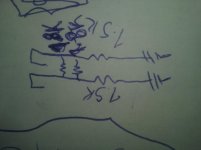
Oh, and to keep roughly the same linearity / non-linearity in the paralleled triodes as in the single triode, do this to keep the currents of each triode about the same:
Use individual 1640 Ohm resistors for each cathode, not two cathodes strapped to a common 820 Ohm resistor.
Also that makes it easy to measure the two cathode voltages and see if you have a 'bad' triode that is either hogging all the current, or is weak (loafing).
I did make an assumption, I thought you wanted the same sound with paralleled triodes versus a single triode.
There is an interesting story behind this....That means the linearity and/or non-linearity of that stage is exactly the same...(Ed: for paralleled triodes with halved cathode and anode load resistors.)
Many tube guitar amp designers believe that their amps will somehow sound richer, better, have more magic "mojo", if they parallel the two triodes in one 12AX7, and halve cathode and anode resistors.
When I first encountered this myth, it left me mystified. It's quite obvious that if the two triodes in one 12AX7 are identical, then paralleling two of them and halving anode and cathode loads should change absolutely nothing, distortion-wise. The tube characteristics remain the same, the bias point remains the same, and the only actual engineering benefit is a trivial 3 dB improvement in signal-to-noise ratio.
(This occurs because of the way independent noise sources add - not linearly, but as the root of the sum of the squares. The result is that the summed signal currents from the two triodes double, but the summed noises only increase to the square root of two (1.4142...). Net result, the S/N ratio is better by a factor of 3 dB.)
Now, if the 12AX7 is poorly manufactured, and the factory has poor quality control, then the two separate triodes in the glass bottle may not be very well matched. And if this is the case, paralleling the two of them will produce something slightly different than either one by itself.
But - there is no guarantee that this will sound better than one triode by itself! It might just as well sound worse, or the change may be too small to be audible. Also, this entire concept is a gamble, a roll of the dice, since it depends entirely on the unwanted and accidental mis-match between the two supposedly identical triodes in one 12AX7. It is most certainly not engineering; it is gambling.
So why does the myth of the magic sound of paralleled triodes continue to persist? Probably for the same reason that every newspaper I've ever encountered still publishes an astrology column, and people continue to read them!
This is another one of those weird things you find in valve guitar amps. Because valves are often driven into positive grid voltage territory, interstage coupling caps start to charge up due to the one-way flow of grid current. That voltage now starts to affect the bias of the subsequent stage (biasing it colder.) This in turn changes the distortion from the tube, in a dynamic way that varies with signal level, adding some life to the otherwise monotonous sound of a bare electric guitar....68k and series 1 nF cap are driving...high impedance when it is less than 0V with respect to its cathode...low impedance when the grid goes positive with respect to its cathode.
And the value of the grid stopper affects this - it changes the time-constant of the circuit, i.e. it changes how quickly or slowly this dynamically changing distortion occurs after a note is picked. Older, slower styles of music (such as electric blues) typically sound good with longer time constants, while fast newer styles (such as shred or fast metal) typically want very short time constants in order not to blur together the fast-picked guitar notes.
-Gnobuddy
Gnobuddy,
And Psicopanque,
Thanks for the good discussions.
Guitar amps explained and discoveries made.
Sometimes I can learn.
I like the mention of gambling too.
For Hi Fi amps: paralleling triodes; and drawing of grid current for RC coupled stages
need to be dealt with properly too.
In Hi Fi I consider the best policy is to keep from gambling.
Whenever someone has a Hi Fi amp that has RC coupling, and he turns it up so high as to draw grid current, I have 2 solutions. Either turn the volume down, or get a more powerful amp. Otherwise, it is not Hi Fi. Take the 'gamble' out of it.
When someone is designing, building, or purchasing a Hi Fi amp, if the amp uses parallel triodes, or he is considering paralleling triodes, I recommend the following:
Use individual self bias resistors and individual bypass caps (if using bypass caps),
a self bias network for each cathode.
That makes it easy to see the amount of current in each cathode. Just read the voltage across the resistor.
That takes the 'gamble' out of it (bad current balance? Then replace the tube with a better balanced one).
And now, most important . . .
Psicopanque, have we answered your original question?
(I do get so very carried away, sorry).
Last edited:
Some smart person said that a tube guitar amp was basically a part of the instrument, and not an amplifier in the normal sense at all.
I too originally came from the world of Hi-Fi, and I found that this viewpoint helped me to begin to make sense of all the peculiar things that go into tube guitar amp design.
Hi-Fi is, in my world, very simple. Flat frequency response 20 - 20kHz, THD below audibility, you're pretty much done. It was hard to achieve in 1960, but these days, even cheap little chip amps can do it.
Leo Fender mostly stole Hi-Fi circuits out of the back of the tube catalogs at first, but the music changed, and squeaky-clean guitar tone is not what most guitarists want these days.
So now tube guitar amp design is much more complicated. You want to make the tubes misbehave, but misbehave in ways that guitarists and audiences like. Decades ago, the preamp in the Marshall 2203 / 2204 had already evolved far from any Hi-Fi roots; you had one triode biased extremely cold, another biased extremely hot, both of them distorting like crazy, and the combination of the two distorting and compressing the guitar signal so much that instead of Leo Fender's "surf clean" tones, those Marshall amps spat out the roaring sounds of what we now call classic rock.
And now? Electric guitar has disappeared from most popular music. Guitarists no longer make any money, and don't become famous. People still build fifty-year-old tube guitar amp designs. You can still buy brand-new tube guitar amps, but they are very expensive, and most cater to the past, rather than looking ahead to new engineering possibilities.
IMO, the handwriting has been on the wall for a while - tube guitar amps, already a small niche, are going to slowly become even more niche. There will be a few out there for a while, just as there are still people with horses. But few people use horses for their primary transportation any more, and pretty soon, few guitarists will use tube guitar amps as their primary music-making technology. The number of electric guitar players itself is dwindling, and more and more of them will end up using a solid-state, digitally modelling guitar amp. Amps like the Boss Katana 50 are finally good enough to wean more guitarists away from tubes altogether.
But I can't build a Boss Katana at home. The mathematics and software used to make a digital signal processor sound like a box full of overdriven vacuum tubes is secret, and complicated, and hobbyists are not going to be able to duplicate the thirty years of effort put in by companies like Roland (Boss).
-Gnobuddy
awww man, i swear that you reside in my heart and thanks again for saving me alot of time and sorry to bother everyone with my questions based in philosophical thoughts to apply into the fact of this is one road to bring our dreams into reality, but i promise i wont bother for much longer since i've sucessfully designed my perfect amp based on plexi style of a el84... this one i can sen u schematic its the one i used for most recent releases of my band, this one of our discussion is in progress and disassembled above the living room table making my wife and drummer go nuts, this amp of parallelled triodes is meant for pure rawness of the instrument and as you stated, not a clean amp, but a flat one that can go mellow and shiny like a simple microphoton fluctuating line when i subtly diagonally slide the pick on the string, to wild magmatic structure of thunderbolts of madness! the plexi one i mentioned has two stages of gain and tmb tonestack, but no master volume besides a fixed high wattage voltage divider before the LTPI grid input cap and many other diffrrrnces i dont even know why i refer to it as 'plexy-style' anymore
BUT i must persuade you into considering not using horses as a comparison because a horse is alive, regenerates, is a masterpiece of the almighty thus the techonogies that we use for substituition of the workhorse really seem to accomodate our commodities (we shouldve never enslaved the Horses anyway!! what if they get mad of our lack of spirituallity and decide to end us with some secret plot?!) and we are already a creation, so comparing a [creation] with a [creation of a creation] is too much kindness to the cause of the TUBEESS
my suggestion is to compare a SW.500 revolver with the infamous desert eagle pistol or something better than remembering us that mankind builds guns and show appreciation for the tool
but tubes are a creation and this stuff you mentioned thats inside boss katana might be seen as very handy if you want to be a painter with alot of artifficial colors that will never be able to paint what we see with our souls and experience with our senses through our organs, are creation of the creation, not an upgrade because they arent the same by far in anything, this kind of painter can play with the toy and make friends showing all that plastic colors
why not show appreciation for the poor artist that paints with his own blood in infinite shades based on intensity?
btw i tested the boss katana and i dont want to publically manifest the results of my experience because they worked hard for it and it will not be a gain but a loss to criticise something that at least function
tube amps forever <3
Last edited:
There is an interesting story behind this.
Many tube guitar amp designers believe that their amps will somehow sound richer, better, have more magic "mojo", if they parallel the two triodes in one 12AX7, and halve cathode and anode resistors.
When I first encountered this myth, it left me mystified. It's quite obvious that if the two triodes in one 12AX7 are identical, then paralleling two of them and halving anode and cathode loads should change absolutely nothing, distortion-wise. The tube characteristics remain the same, the bias point remains the same, and the only actual engineering benefit is a trivial 3 dB improvement in signal-to-noise ratio.
(This occurs because of the way independent noise sources add - not linearly, but as the root of the sum of the squares. The result is that the summed signal currents from the two triodes double, but the summed noises only increase to the square root of two (1.4142...). Net result, the S/N ratio is better by a factor of 3 dB.)
Now, if the 12AX7 is poorly manufactured, and the factory has poor quality control, then the two separate triodes in the glass bottle may not be very well matched. And if this is the case, paralleling the two of them will produce something slightly different than either one by itself.
But - there is no guarantee that this will sound better than one triode by itself! It might just as well sound worse, or the change may be too small to be audible. Also, this entire concept is a gamble, a roll of the dice, since it depends entirely on the unwanted and accidental mis-match between the two supposedly identical triodes in one 12AX7. It is most certainly not engineering; it is gambling.
So why does the myth of the magic sound of paralleled triodes continue to persist? Probably for the same reason that every newspaper I've ever encountered still publishes an astrology column, and people continue to read them!
This is another one of those weird things you find in valve guitar amps. Because valves are often driven into positive grid voltage territory, interstage coupling caps start to charge up due to the one-way flow of grid current. That voltage now starts to affect the bias of the subsequent stage (biasing it colder.) This in turn changes the distortion from the tube, in a dynamic way that varies with signal level, adding some life to the otherwise monotonous sound of a bare electric guitar.
And the value of the grid stopper affects this - it changes the time-constant of the circuit, i.e. it changes how quickly or slowly this dynamically changing distortion occurs after a note is picked. Older, slower styles of music (such as electric blues) typically sound good with longer time constants, while fast newer styles (such as shred or fast metal) typically want very short time constants in order not to blur together the fast-picked guitar notes.
-Gnobuddy
omg dude thanks for this insights, i share your thoughts and for me this is important because it solidifies my belief because i believe you are good in this stuff
Gnobuddy,
And Psicopanque,
Thanks for the good discussions.
Guitar amps explained and discoveries made.
Sometimes I can learn.
I like the mention of gambling too.
For Hi Fi amps: paralleling triodes; and drawing of grid current for RC coupled stages
need to be dealt with properly too.
In Hi Fi I consider the best policy is to keep from gambling.
Whenever someone has a Hi Fi amp that has RC coupling, and he turns it up so high as to draw grid current, I have 2 solutions. Either turn the volume down, or get a more powerful amp. Otherwise, it is not Hi Fi. Take the 'gamble' out of it.
When someone is designing, building, or purchasing a Hi Fi amp, if the amp uses parallel triodes, or he is considering paralleling triodes, I recommend the following:
Use individual self bias resistors and individual bypass caps (if using bypass caps),
a self bias network for each cathode.
That makes it easy to see the amount of current in each cathode. Just read the voltage across the resistor.
That takes the 'gamble' out of it (bad current balance? Then replace the tube with a better balanced one).
And now, most important . . .
Psicopanque, have we answered your original question?
(I do get so very carried away, sorry).
yes my friend thanks and sorry to bother
i just paralled it because this design is for a single stage and tubes are expensive so it would be a waste and i dont want to be a cheapass wasting my time into the craft of a switching and measuring system that enable you to select v1a/v1b for a single triode
SOOOO paralleling is easier hahahaha and if it gives any benefit even 0.00001 is a reward
Sometimes I like to use parallel tubes in my amplifiers.
In 2000, two others and I did some major research of paralleling tubes. There were over 600 measurements of voltage, current, gain, and spectrum; collation of the data; Taylor series math; 3 blind session listening venues; and some inductive and deductive reasoning.
This resulted in us writing the cover article for the [last issue] of Glass Audio: Volume 12, Number 5, 2000. The name of the Article: "Paralleling Tubes Effects".
The real key to paralleling tubes is attention to details. They were covered in the article. (there are more design issues than you might think).
Then I spoke about it at VSAC 2005 in Silverdale, WA.
(Vacuum Tube State of the Art Conference).
I also did a presentation at VSAC 2008 in Vancouver, WA.
I did a talk with computer 'slides' and a projector; then I ran a listening session too (one of the amplifiers used parallel tubes).
Last edited:
Oh, and to keep roughly the same linearity / non-linearity in the paralleled triodes as in the single triode, do this to keep the currents of each triode about the same:
Use individual 1640 Ohm resistors for each cathode, not two cathodes strapped to a common 820 Ohm resistor.
Also that makes it easy to measure the two cathode voltages and see if you have a 'bad' triode that is either hogging all the current, or is weak (loafing).
I did make an assumption, I thought you wanted the same sound with paralleled triodes versus a single triode.
i dont have the parts value for what you've requested for this deed
can it be rk 1.5k
and the bootstrappin' 900?
such as the drawing-thing on attachment?
so the currents balanced are better?
i once pondered if the HUGE improvement of a cent i(1%) n the harmonic content was the wild interaction between the two cathodes glued together as a happy picknik to the rk
but if theres some malfunction/saturation/noise, well... true misbehalfing on the device's functionment caused by that, then it can be good to apply
i dont know, to be honest i didnt understand if its gonna get nasty
but obviously i'll try and test it for like 3 days
and if i use it, then i'll offer a toast in your name
and even if i don't, i'll drink on your name anyway
salute from your brasilian friend
Attachments
Last edited:
i meditated on your words of wisdom
and the conclusion is that i must thank you for this treasure chest
the boostrapping resistor will introduce some degree of phase cancelling to the bias, if the cathodes are 180 degrees out of phase or somethingike that reducing the current that is the same (usually undistorted)
this lights up the signal to saturate less (dreaded blocking excursoon)
so theres more room for bigger coupling caps, enabling more bass
and i experimented ppimv volume with pot between coupled power amp plates and this resistor increases the harmonic content
SOOO CONGRATZ! it seem to be a flawless plan
- Status
- This old topic is closed. If you want to reopen this topic, contact a moderator using the "Report Post" button.
- Home
- Amplifiers
- Tubes / Valves
- values for parallel triodes into LTPI